Assembly
Soldering
If you do not have experience with soldering, please refer to this Quick Start guide.
General Assembly
First we will solder the parts that are the same on both the wired and wireless variants.
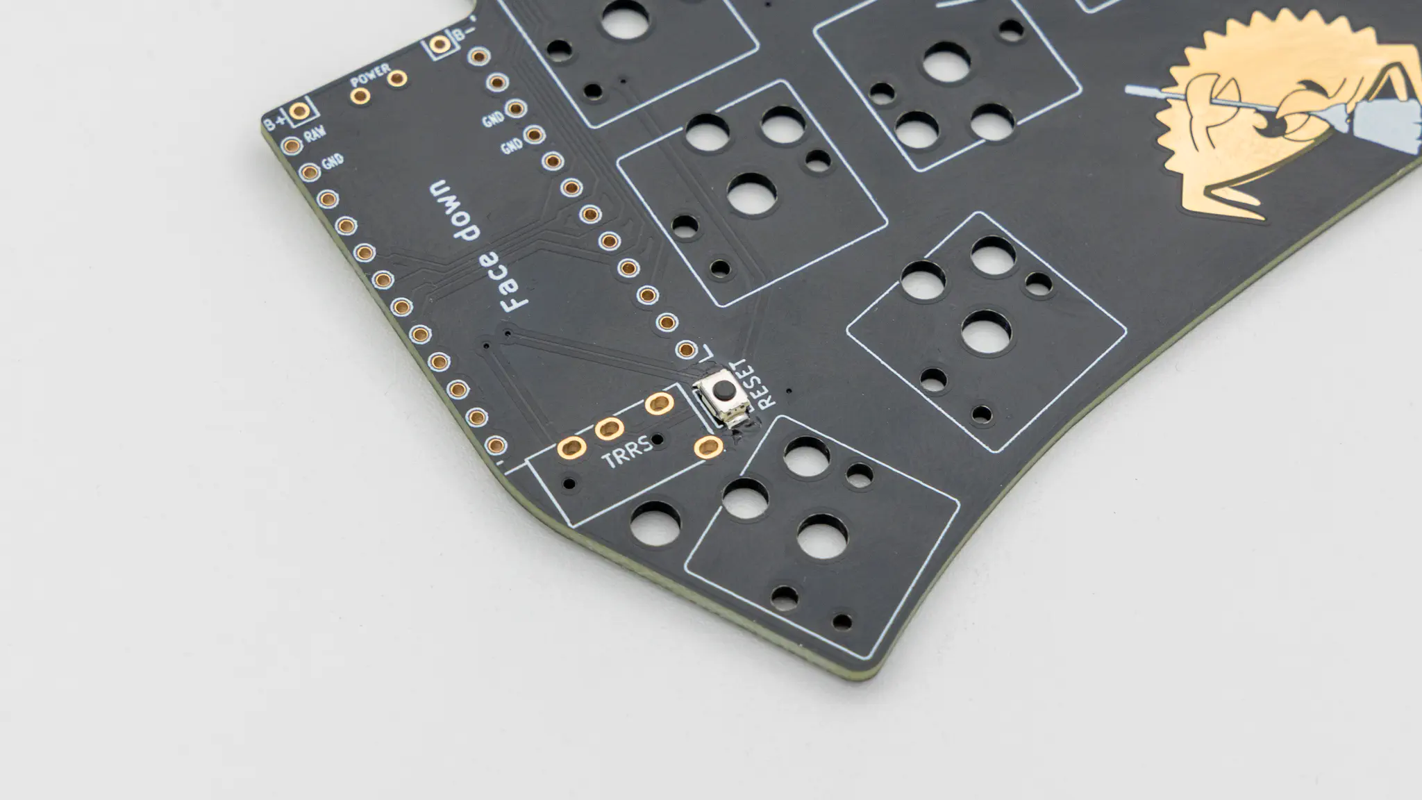
Reset Buttons
Solder on the reset buttons.
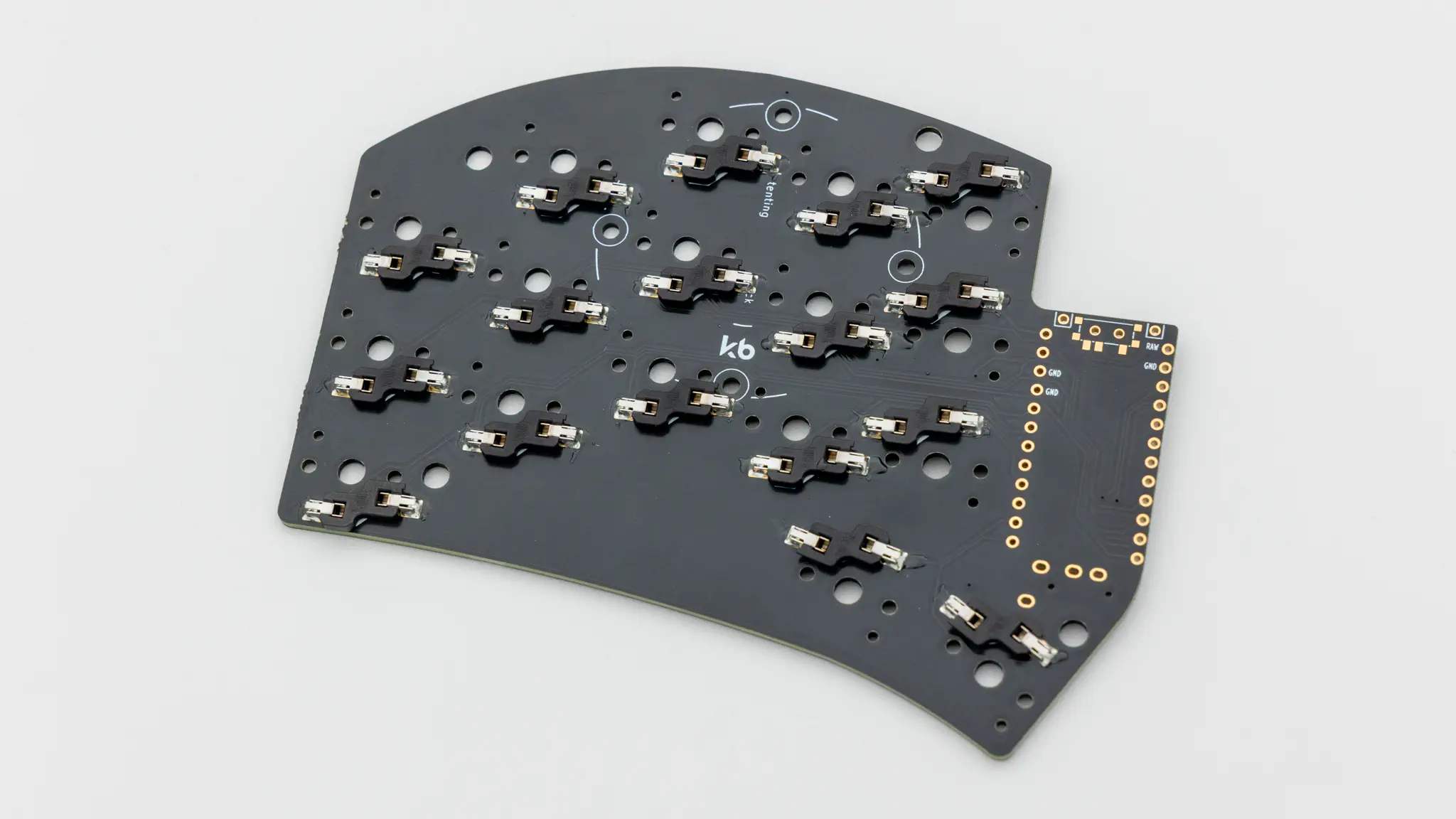
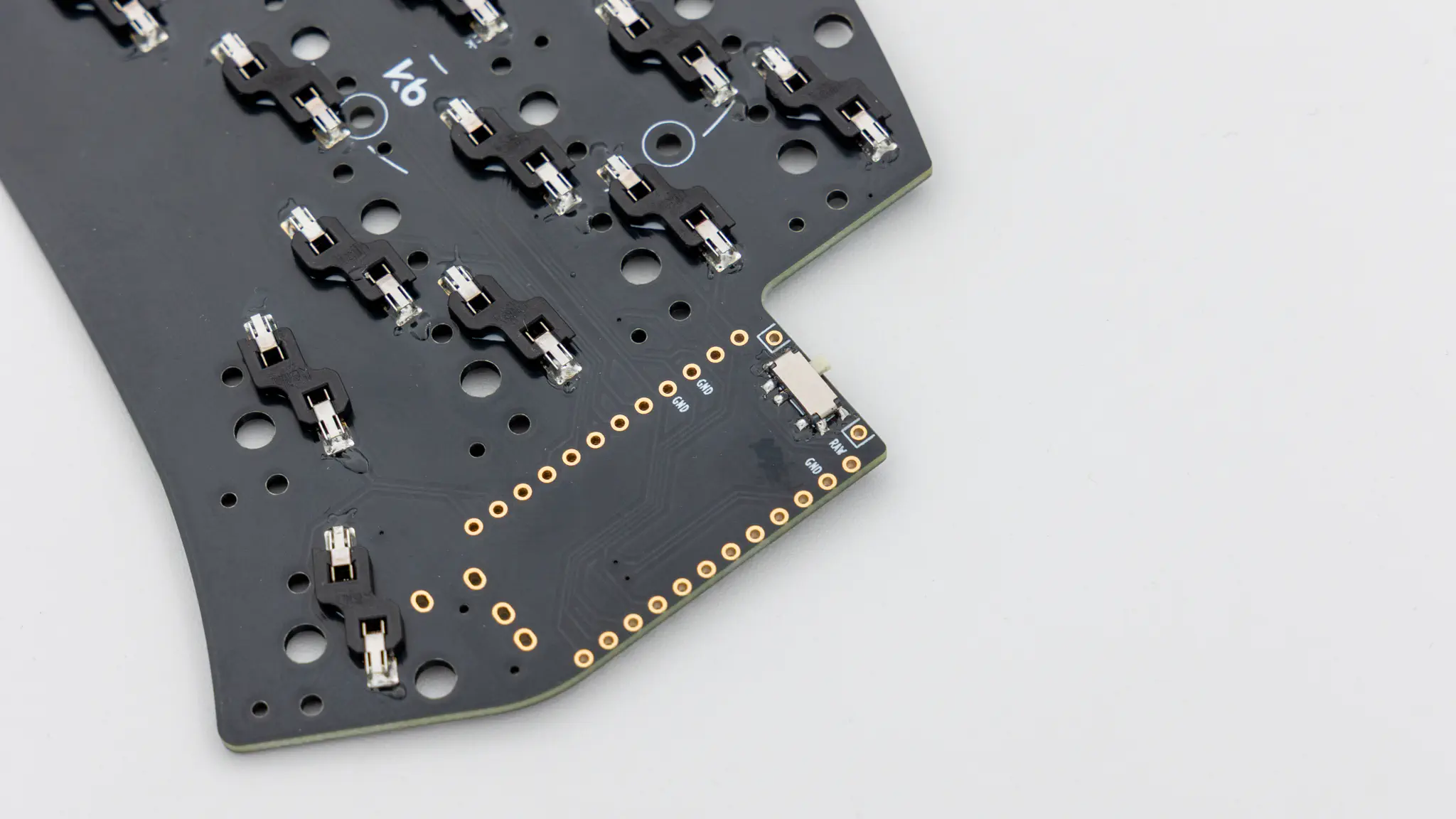
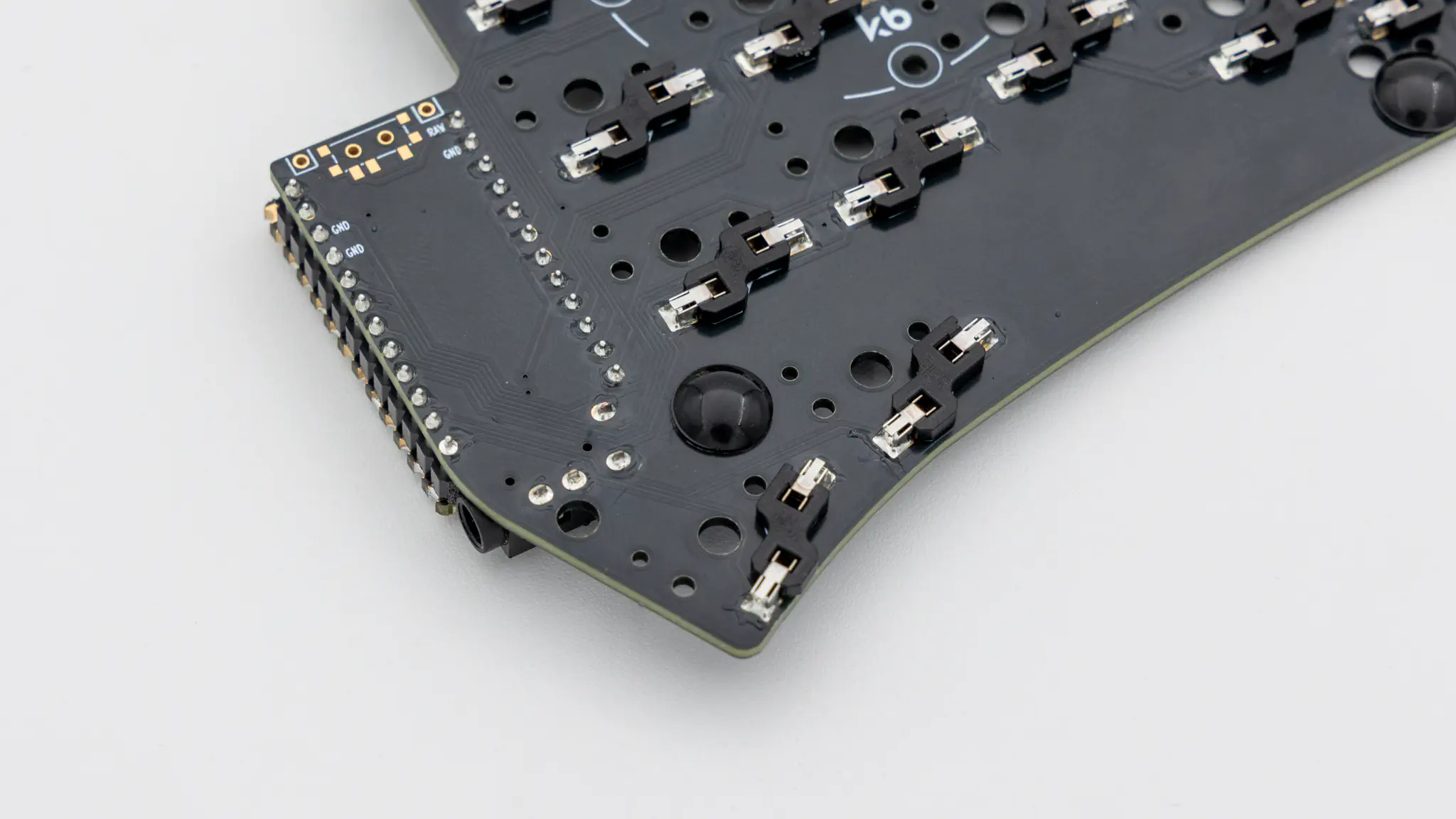
Hotswap Sockets
Solder on the hotswap sockets. You can find instructions for that here.
Please skip to this part now if you are building a wireless Sweep.
Please skip to this part now if you are building a wired Sweep.
Wireless
All of the steps in this paragraph need to be done when assembling the wireless variant of the Sweep.
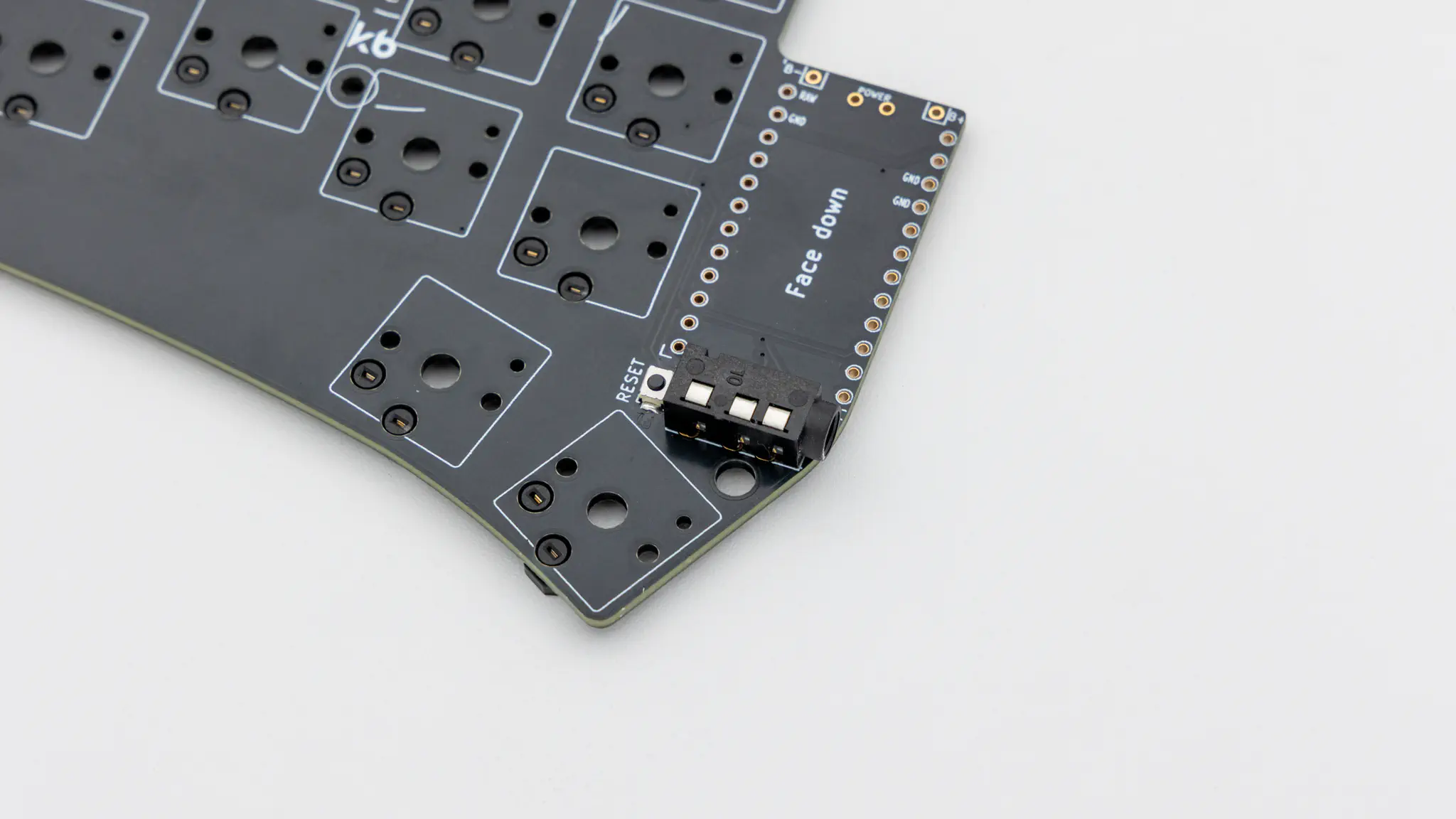
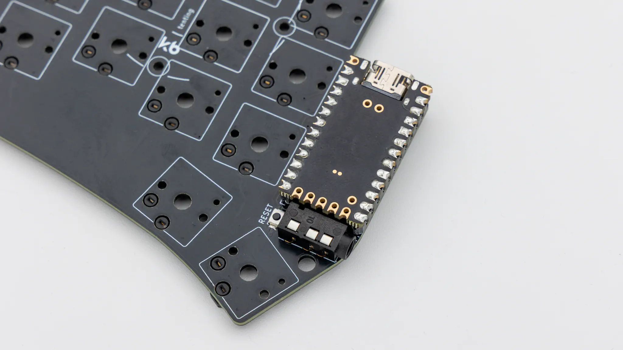
Slide Switch
You will need to solder in the slide switch to be able to power the keyboard on or off. The switch is located on the back of the PCB.
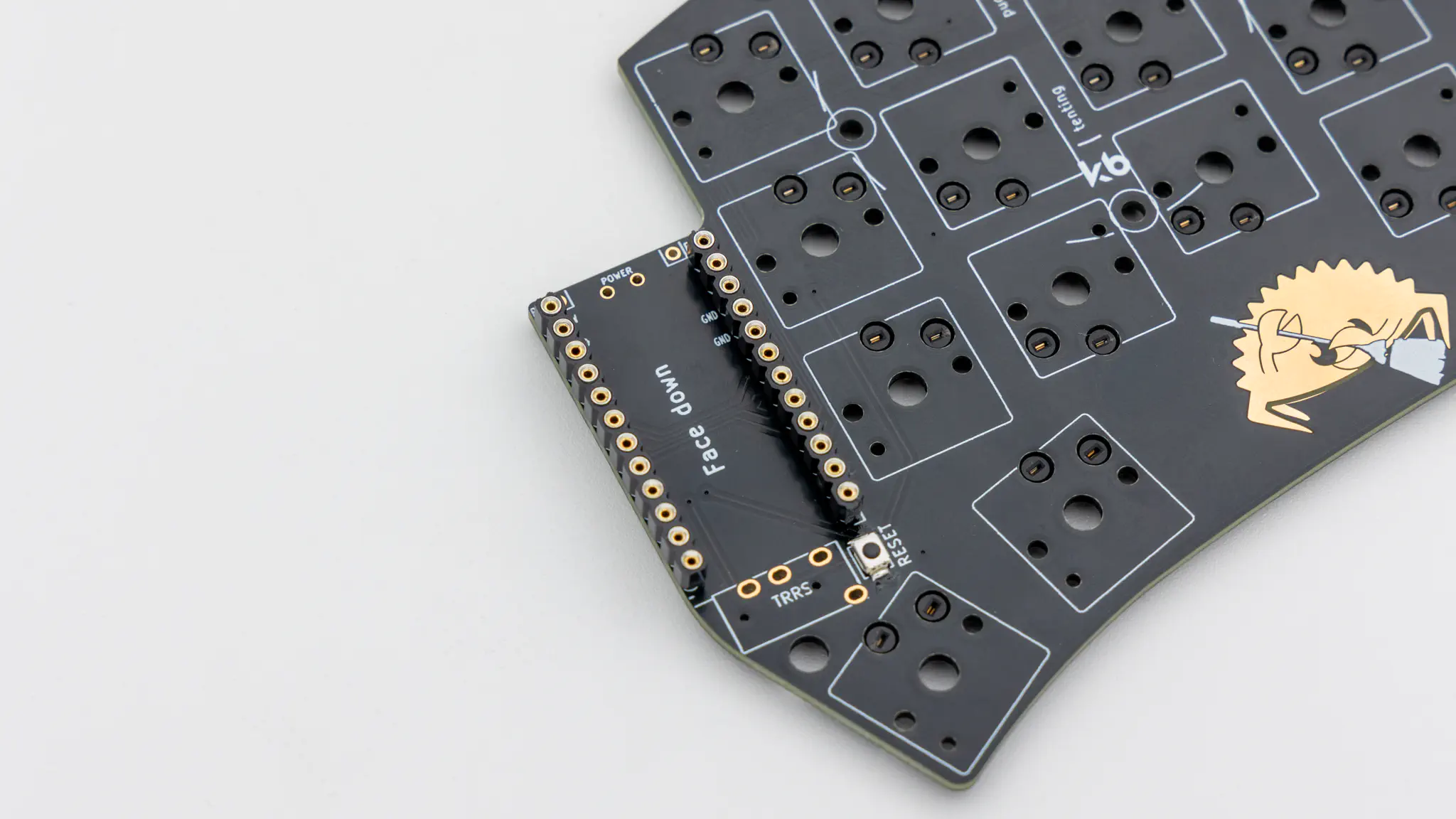
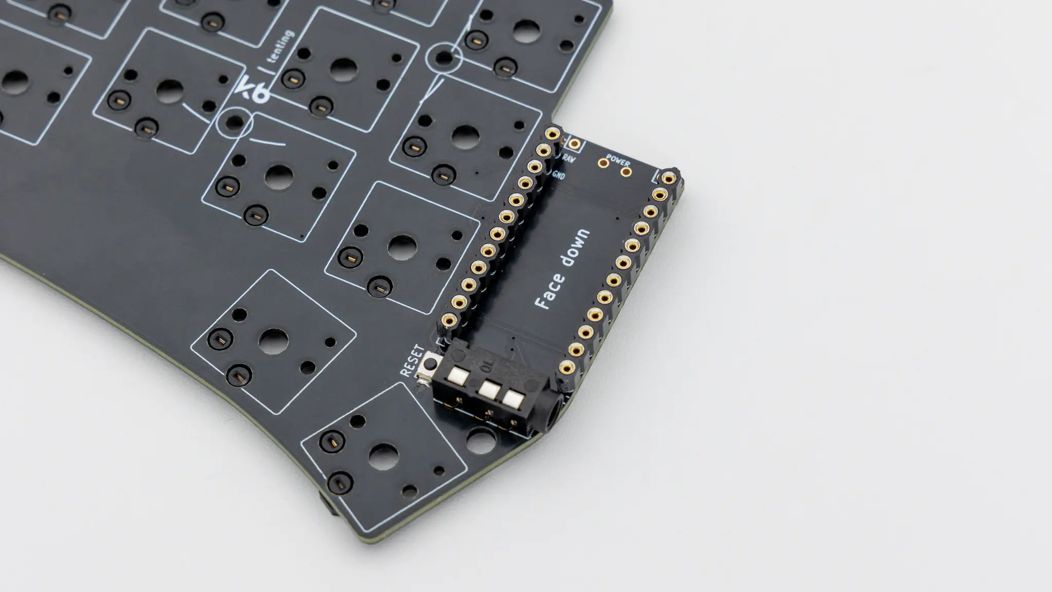
Controller Standoffs
Next solder on the standoffs for your controller. You need to use IC sockets with MillMax pins for this board. Read through here if you have not done that before.
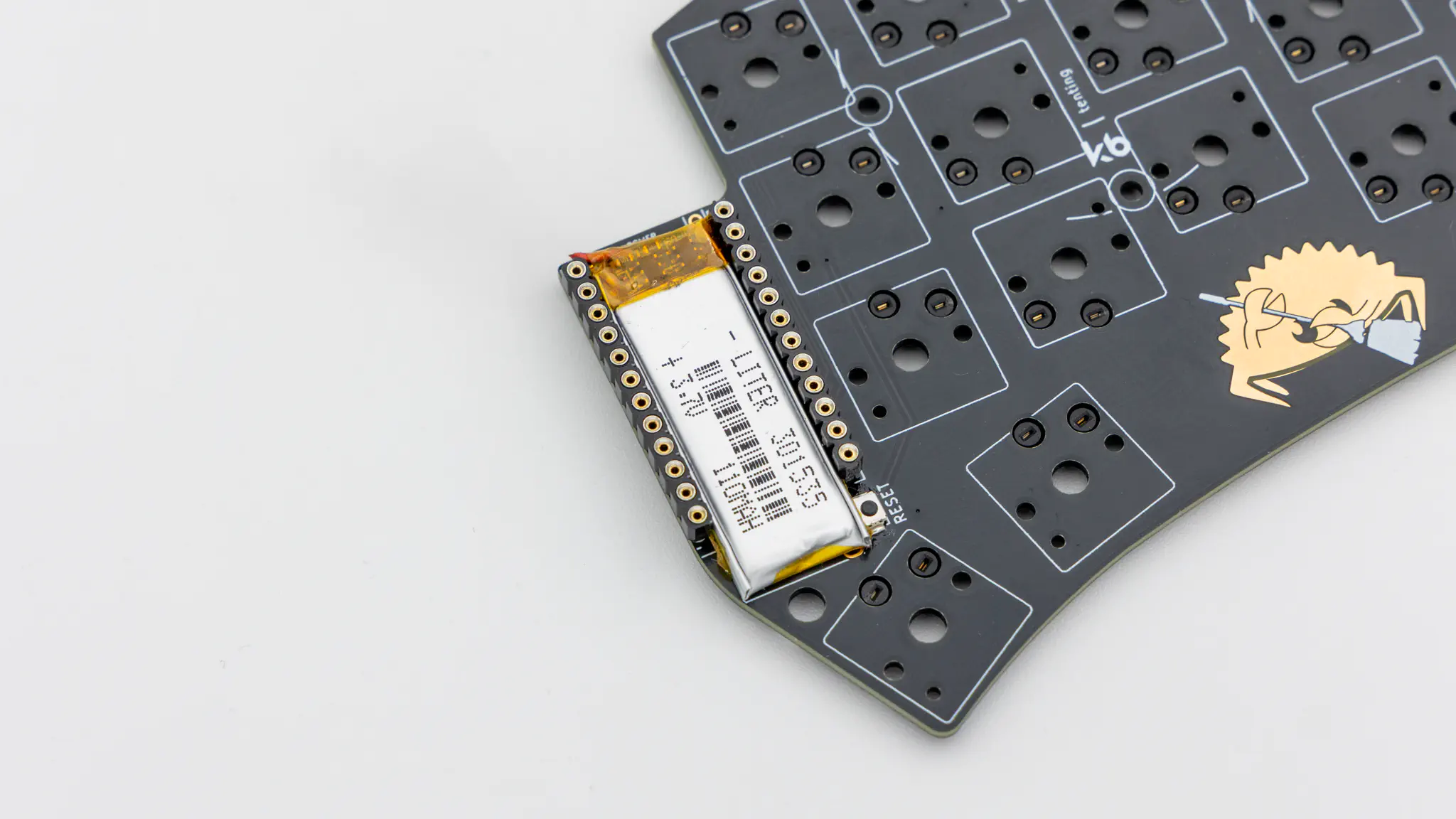
Batteries
If you bought the battery that we suggested, the fit will be quite tight. It’s easiest if you slide it in from the top, since pushing it down will not work. Solder in the batteries on the marked pins at the top.
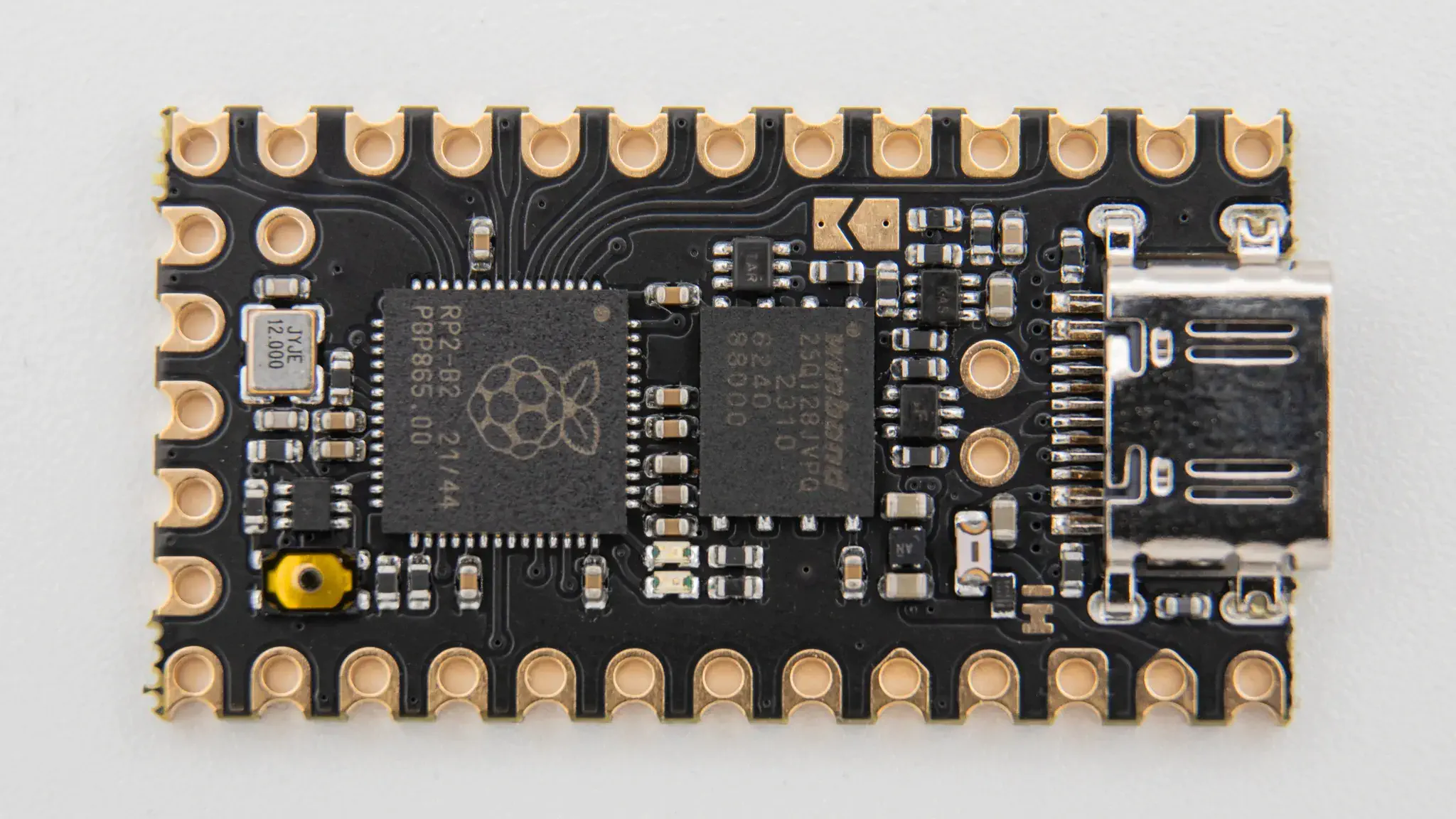
Controller
Before soldering the controllers onto the PCB we should get your controller flashed.
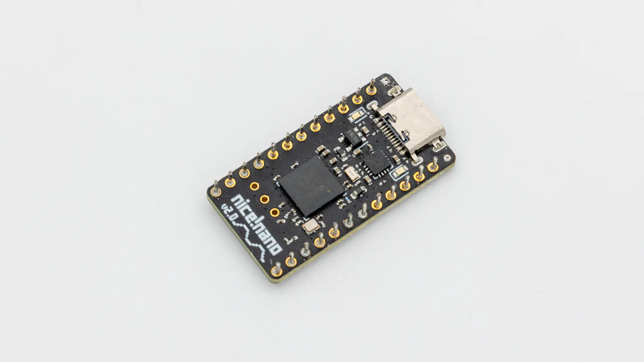
Depending on which controller you use you will have to go about flashing them differently. You’ll have to set up a ZMK user repo to build your firmware. Intructions on how to do that are available here. During the keyboard selection step select the Cradio/Sweep. And instructions on how to flash a controller are available here.
Solder the controller to the headers now. Instructions on how to do that can be found here. When you have the PCB in front of you, the USB port should go to the top of the PCB. You should not see the components of the controller, when it is sitting on the PCB.
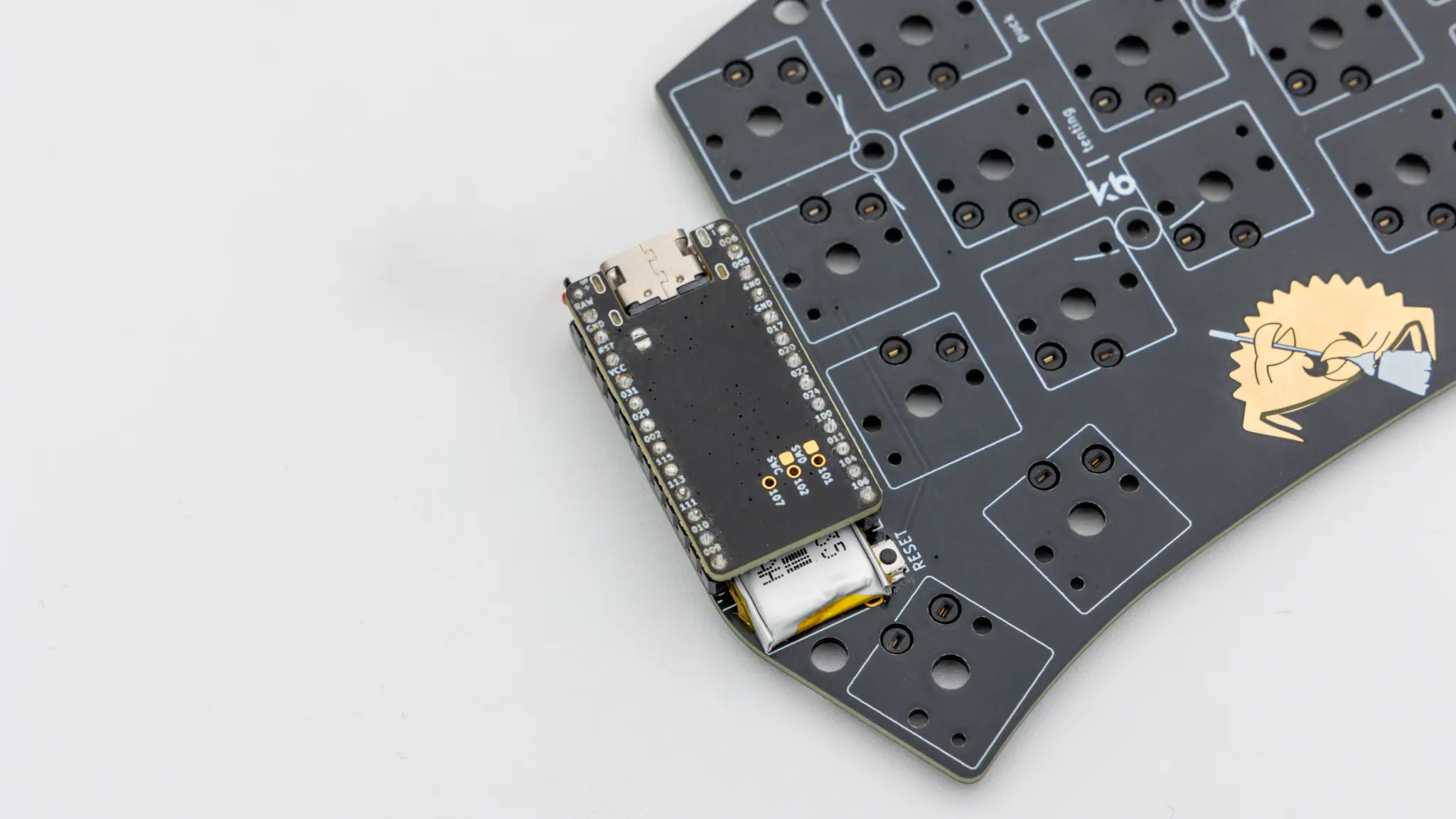
You can now skip to the Final Assembly to continue.
Wired
All of the steps in this paragraph need to be done when assembling the wired variant of the Sweep.
TRRS Jacks
You will need to solder in the TRRS jacks.
Controller Standoffs
Next solder on the standoffs for your controller. You need to use IC sockets with MillMax pins for this board. Read through here if you have not done that before.
Controller
Before soldering the controllers onto the PCB we should get your controller flashed.
You can find the firmware here. And instructions on how to flash a controller here.
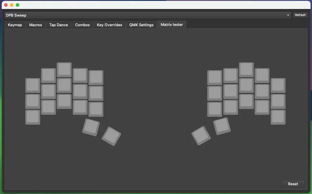
Plug in your controller now and see if it pops up in VIAL.
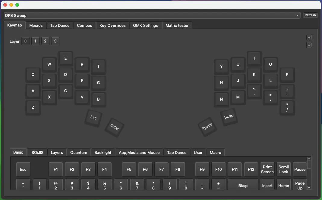
If it does you have successfully flashed your controller.
If your controller is working, you can solder it in. Instructions on how to do that can be found here. When you have the PCB in front of you, the USB port should go to the top of the PCB. You should not see the components of the controller, when it is sitting on the PCB.
When you have your controller soldered in, it is good practice to do a matrix test. Since the Sweep is a split keyboard, you need to plug in the two halves together using the TRRS cable.
You can now continue reading the Final Assembly to proceed.
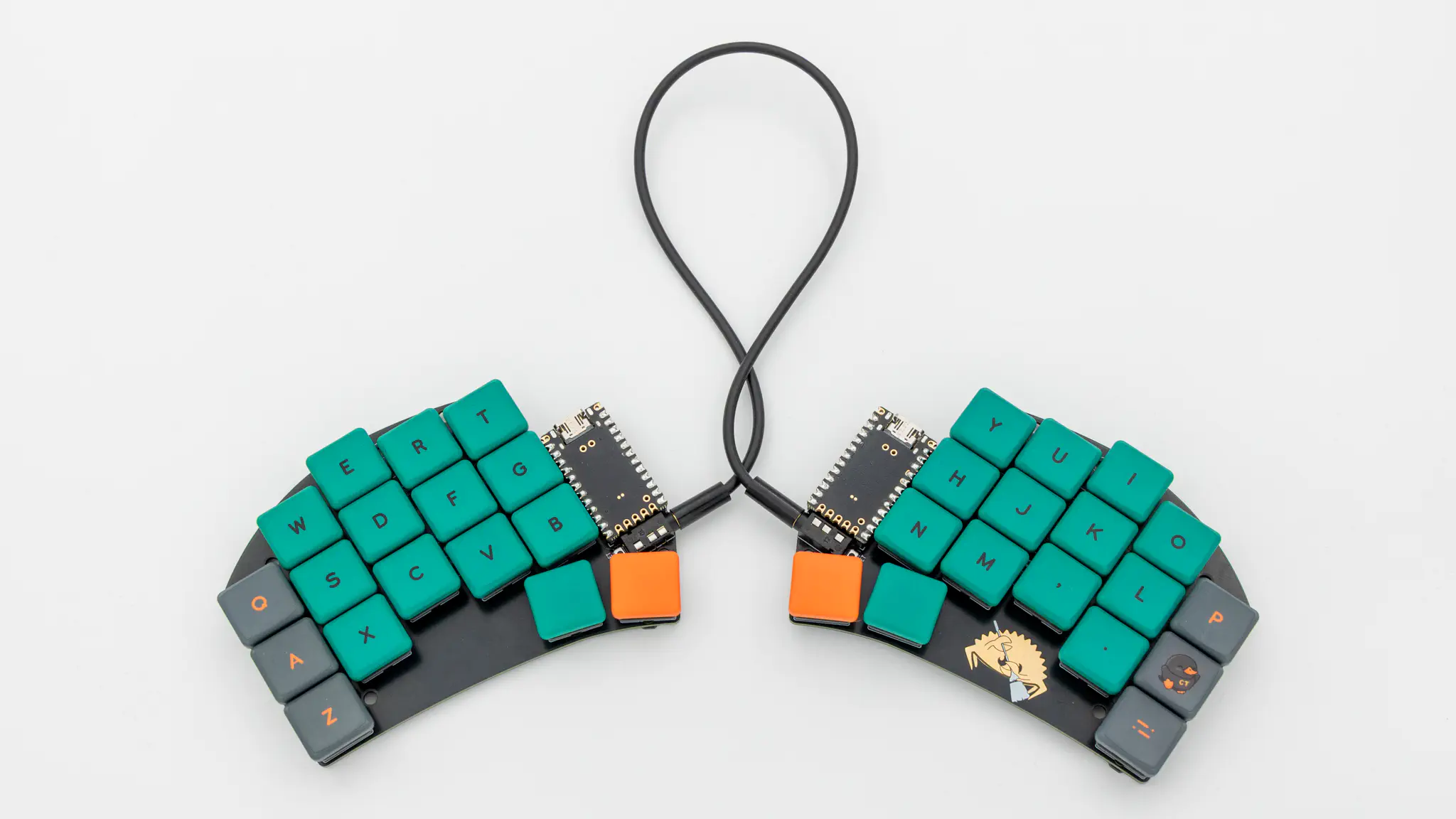
Final Assembly
Start by putting on the rubber feet. We provide 4 feet per side which you can place wherever you want.
After that push in the switches.
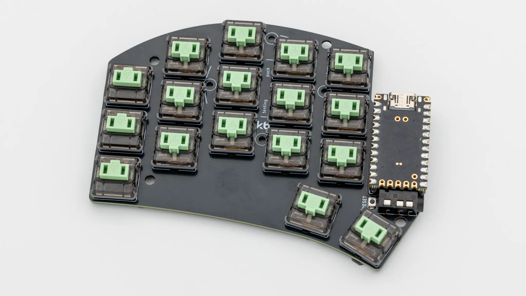
As a last step put on your keycaps.
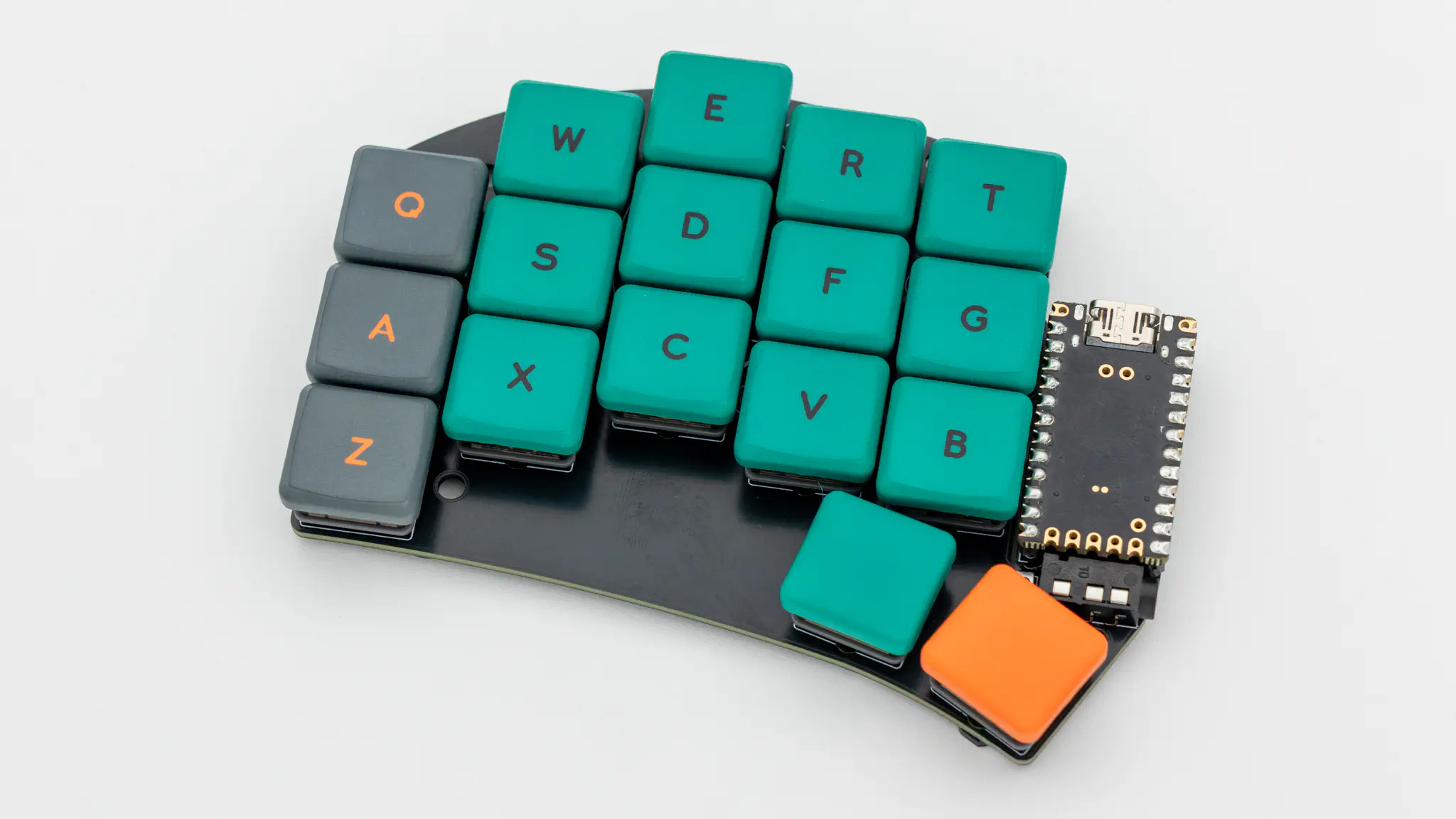
And your Sweep keyboard is done!