Assembly
Before we start the assembly, you need to take apart the case! This is how you will get everything from us:
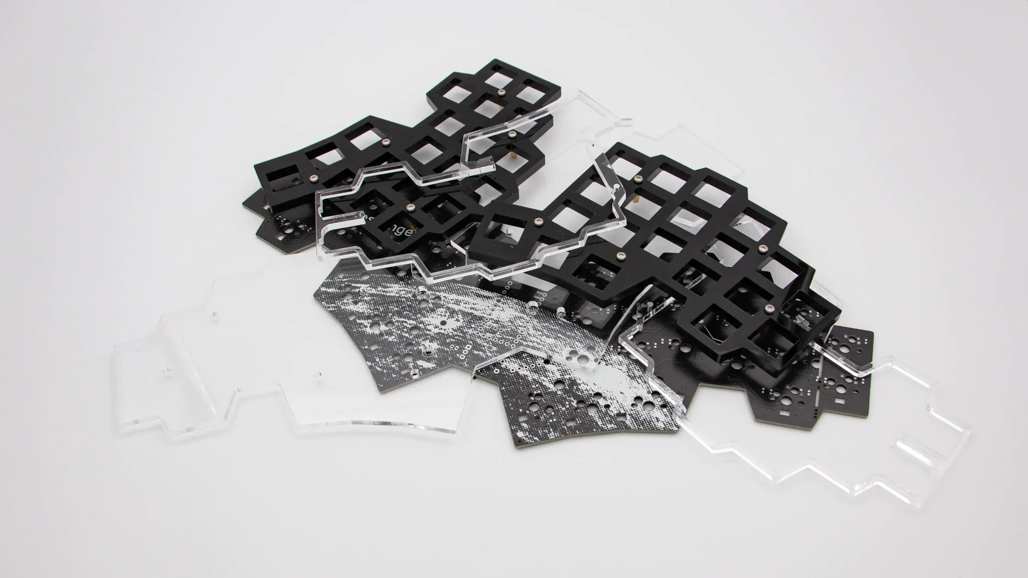
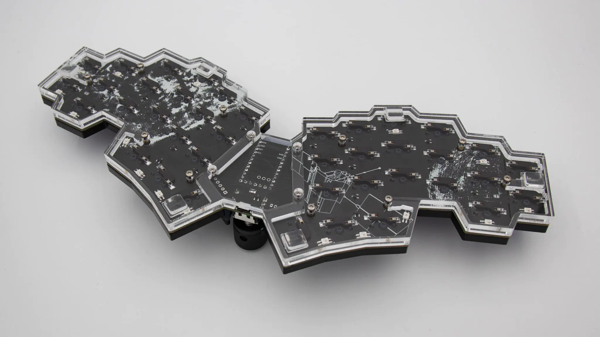
 As you can see all the acrylic parts are stacked together with the PCB.
Please remove the screws from one side and pull apart the pieces. You should be left with 3 bottom pieces, two switch plates, the PCB and most of the hardware. You will then need to remove the plastic film from all of the acrylic pieces!
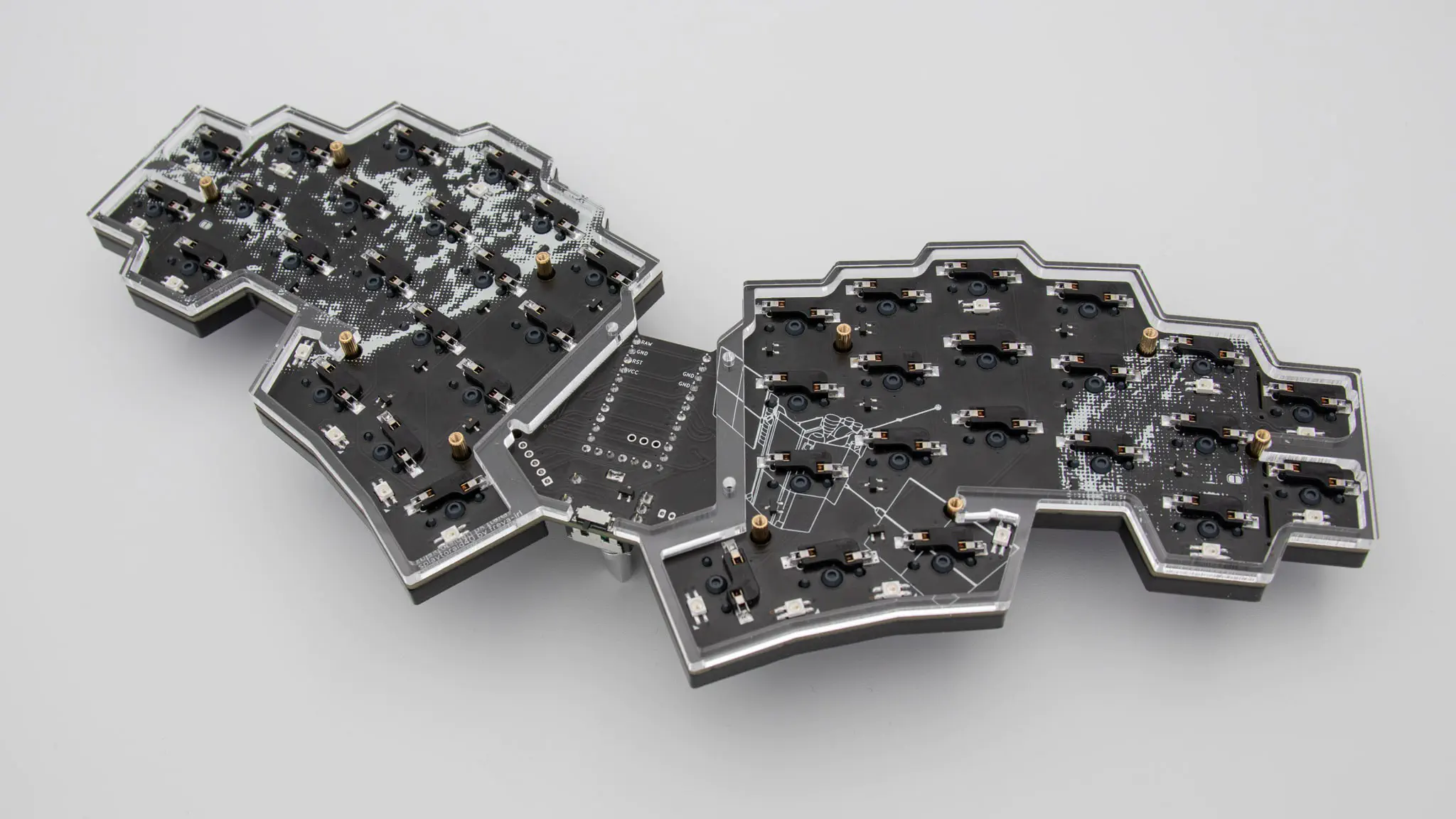
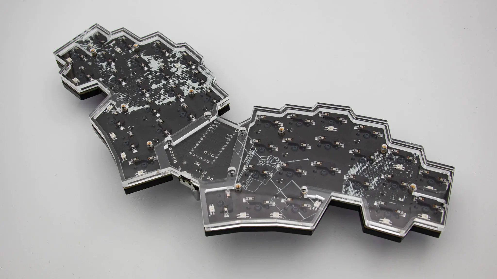
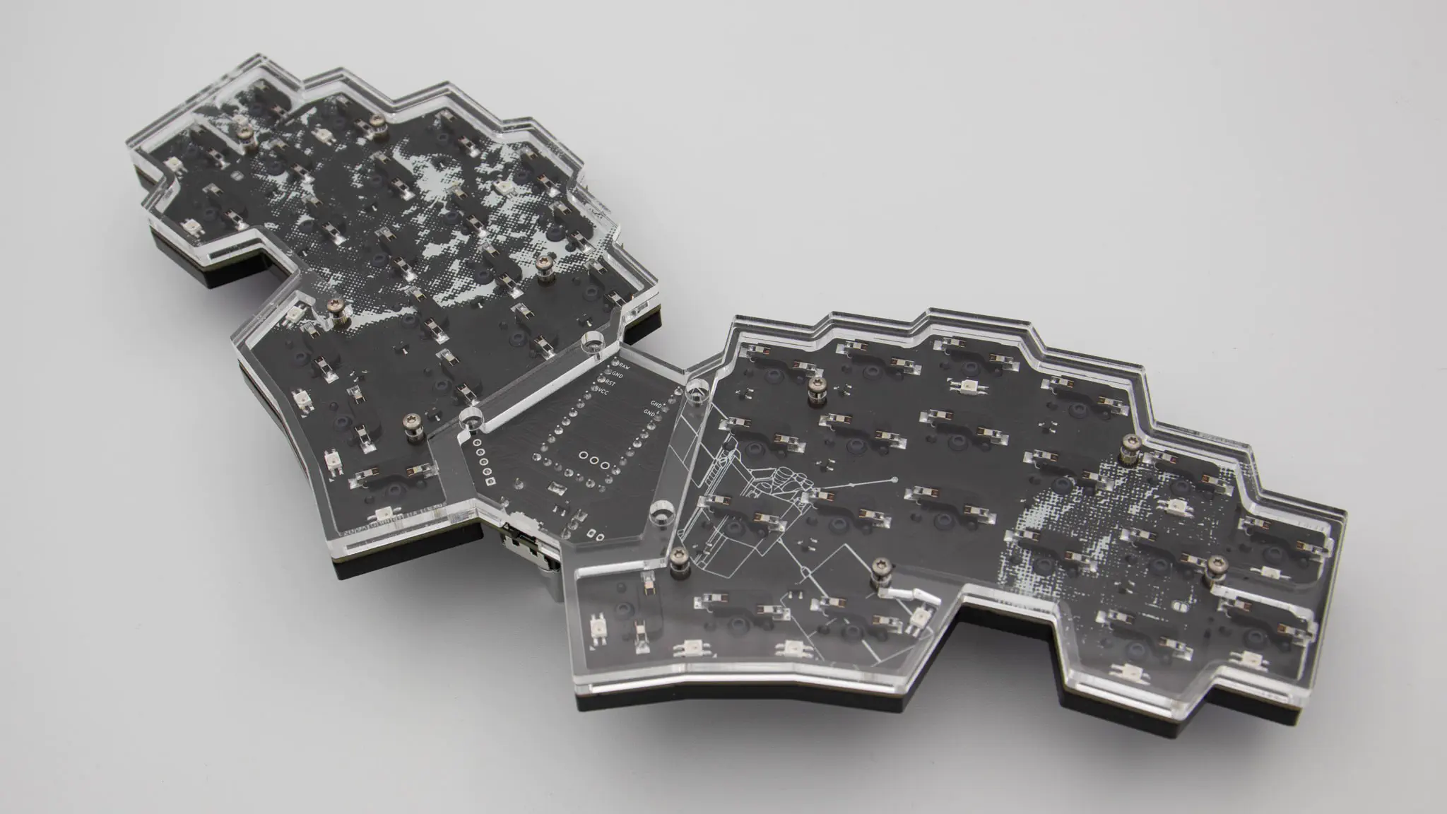
PCB
Let’s start the assembly with the PCB and electronic components.
Controller
Before soldering anything on the PCB we should get your controller ready.
You have to flash the controller. You can find the firmware here. And instructions on how to flash a controller here.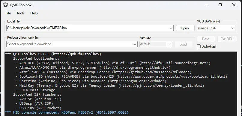
Plug in your controller now and see if it pops up in VIAL.
If it does you have successfully flashed your controller and can move on.
Soldering
There are a few things you absolutely need to solder and a few which are optional. The PCB comes with some components presoldered, so you don’t need to solder a lot.
required
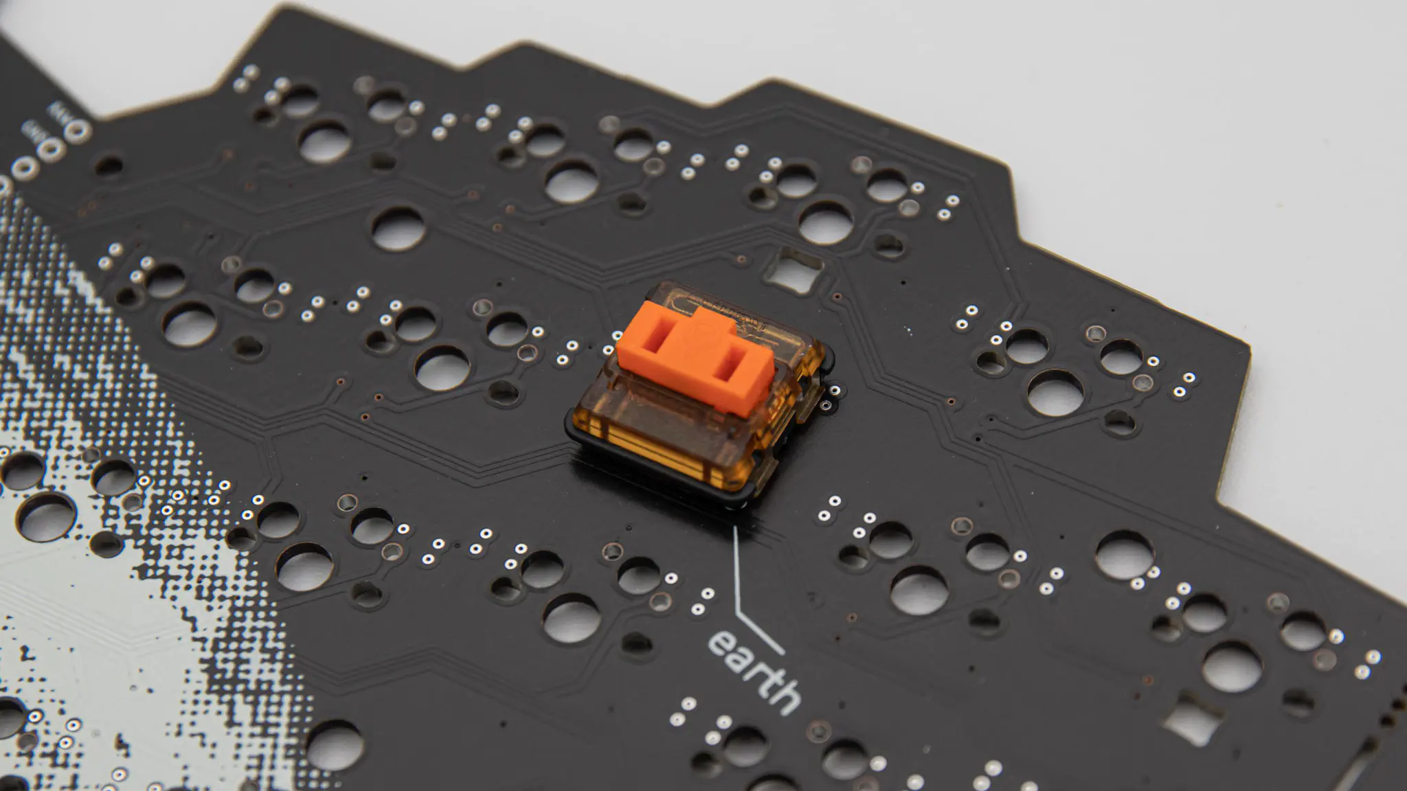
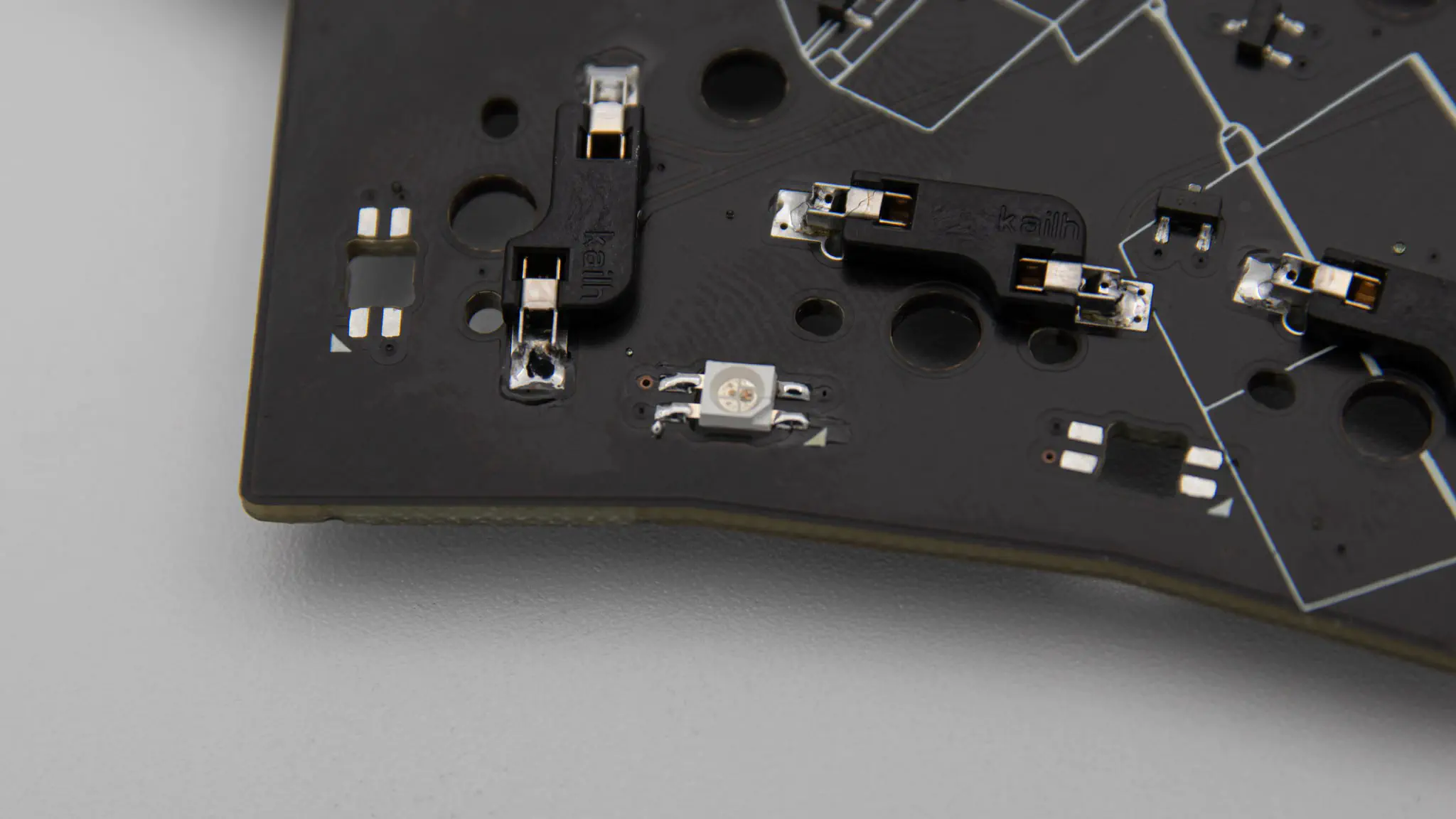
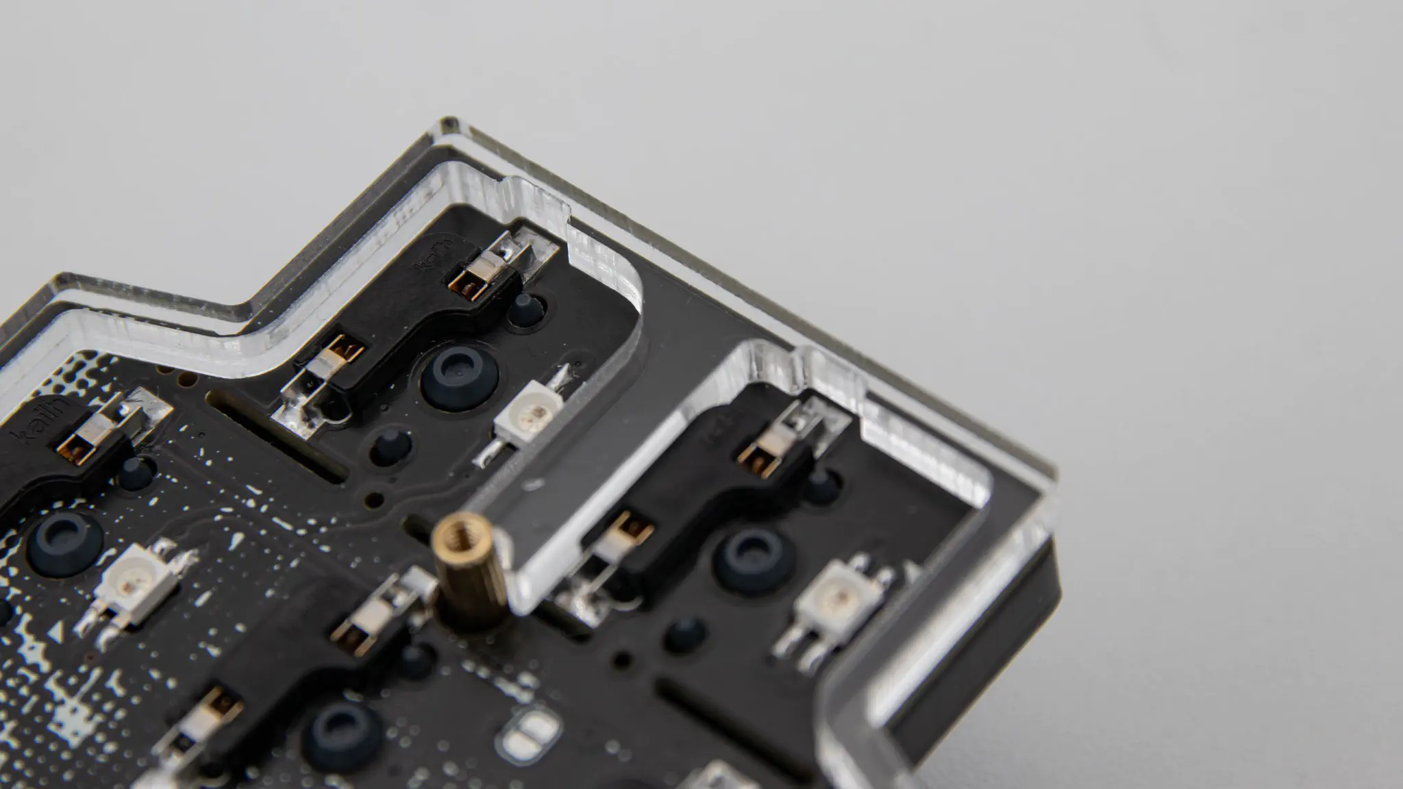
Begin soldering with the hotswap sockets. You can find instructions for that here. If you plan on using choc switches, skip this step.
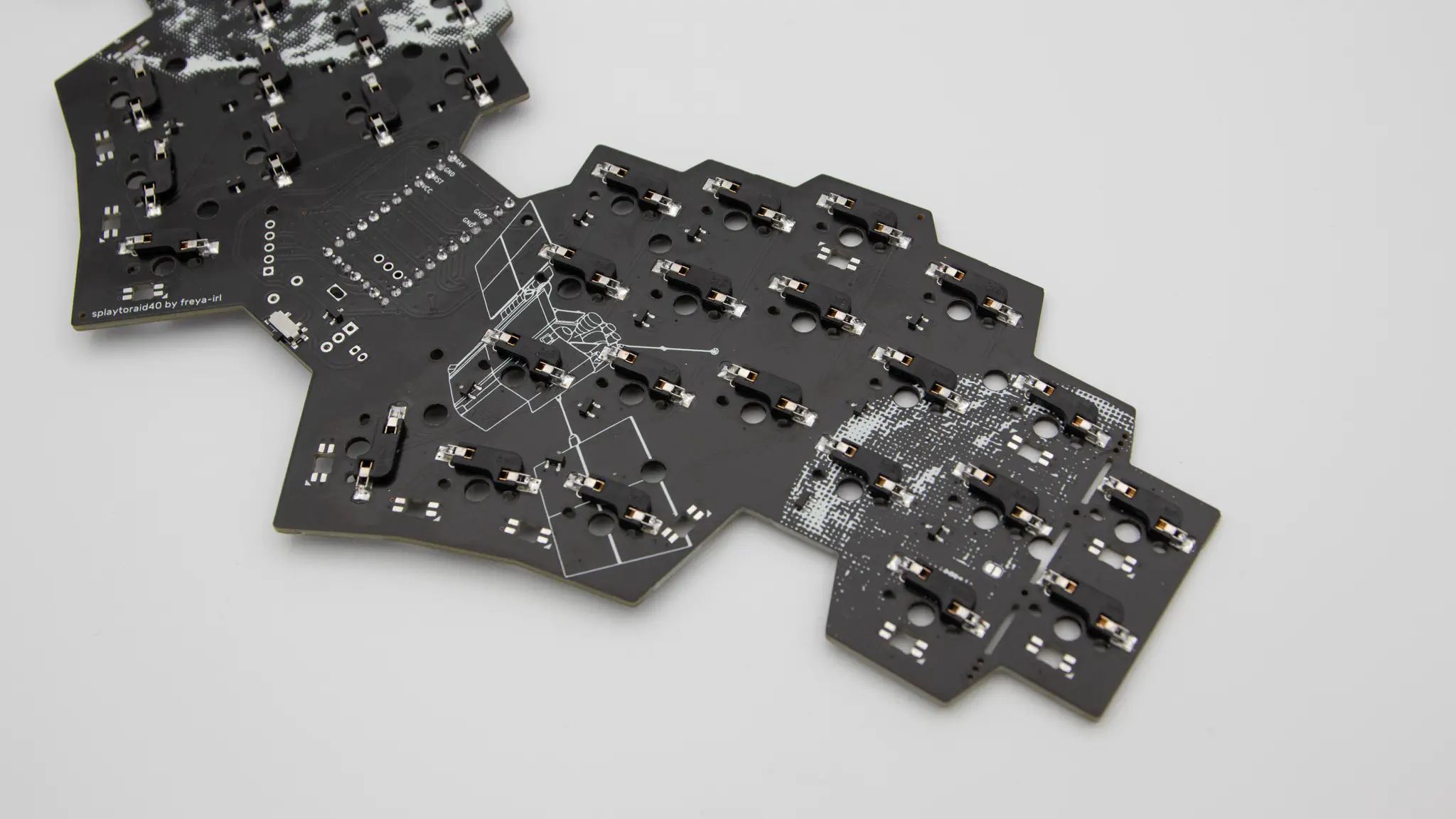
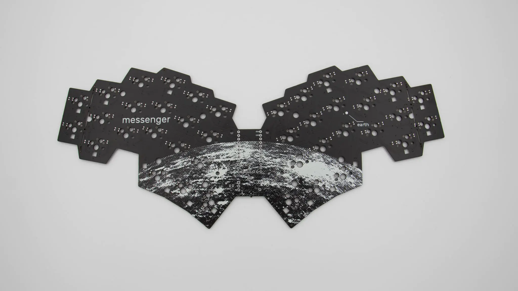
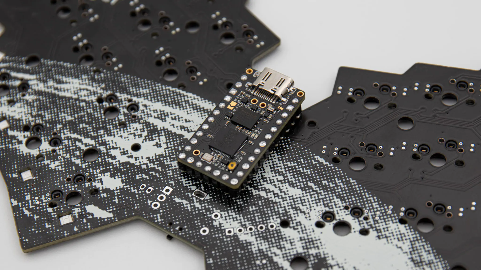
Please solder in the headers for the controller. You can find instructions for that here. The headers go on the front. That is the side with the messenger writing on it.
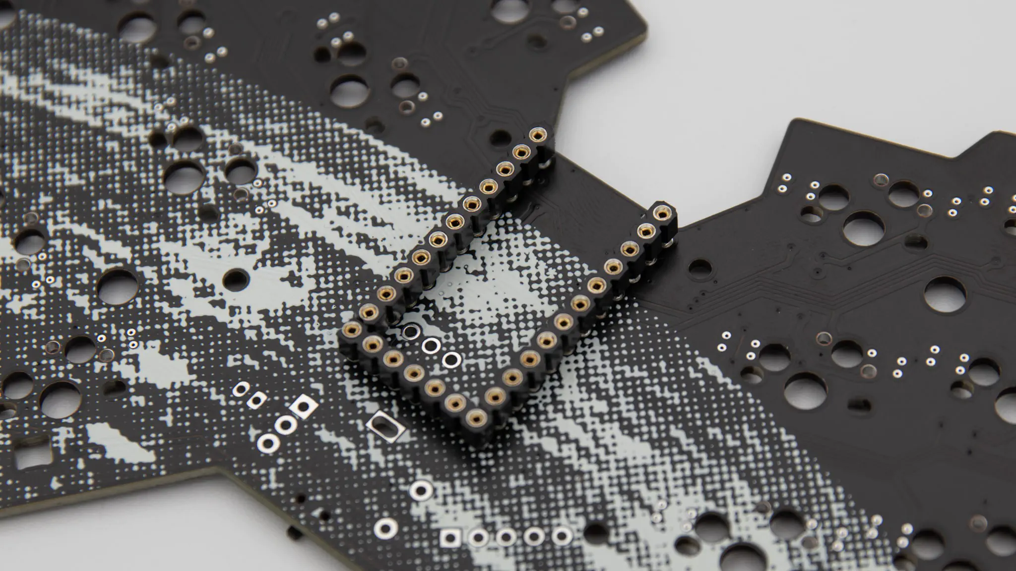
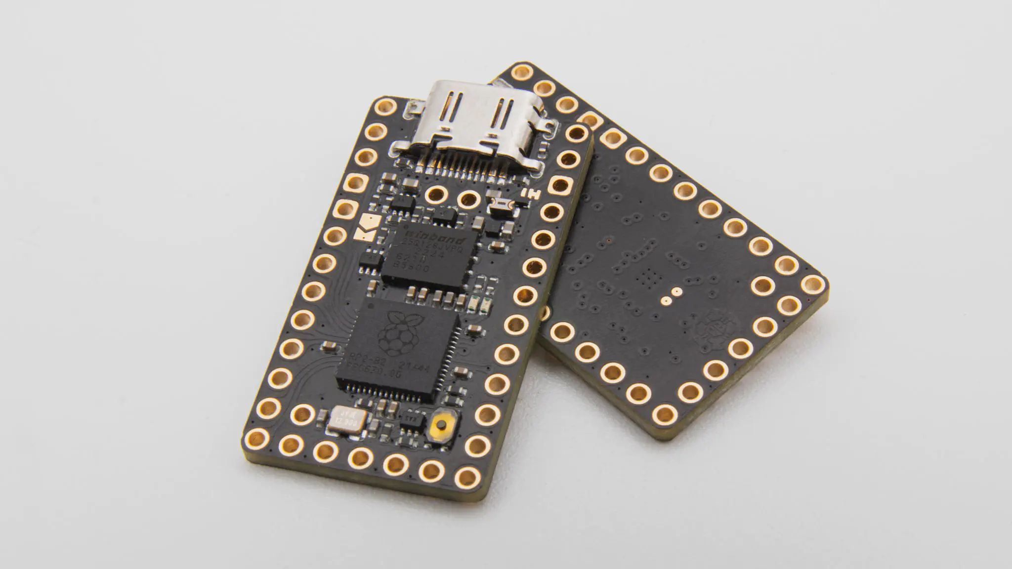
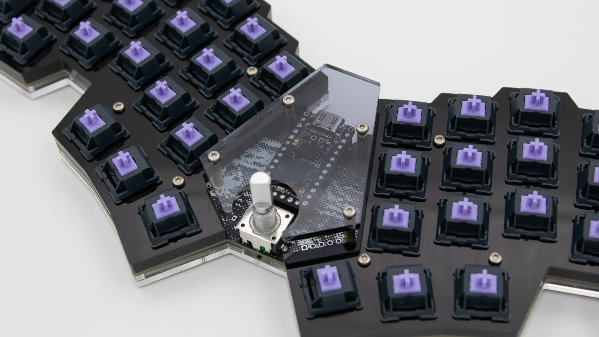
If your controller is working, you can solder it in. Instructions on how to do that can be found here. When you have the PCB in front of you, the USB port should go to the top of the PCB. You should see the components of the micro controller, when it is sitting in the PCB!
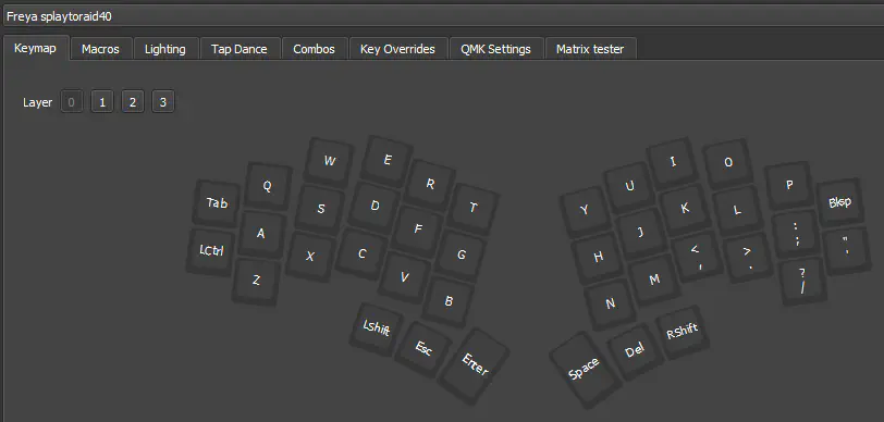
When you have your controller soldered in, it is good practice to do a matrix test.
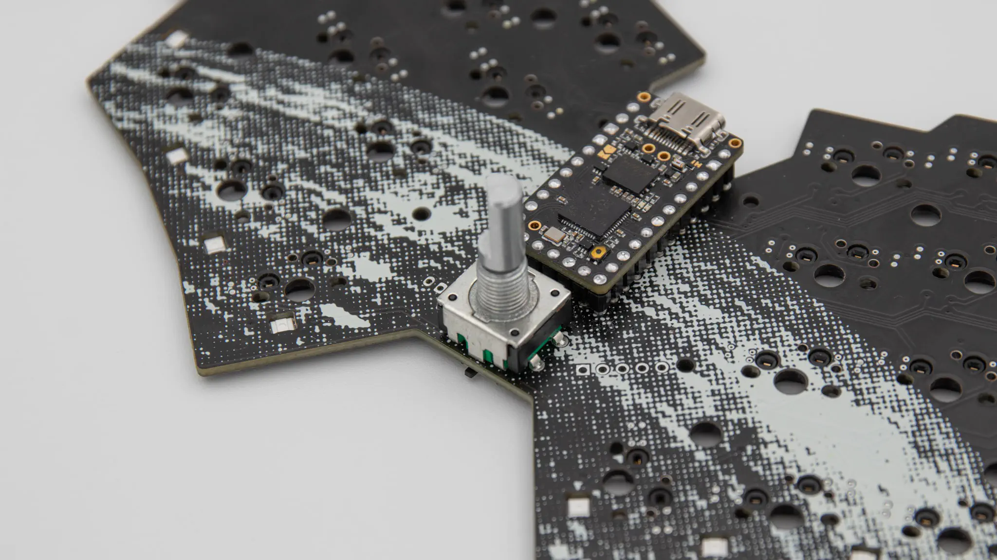
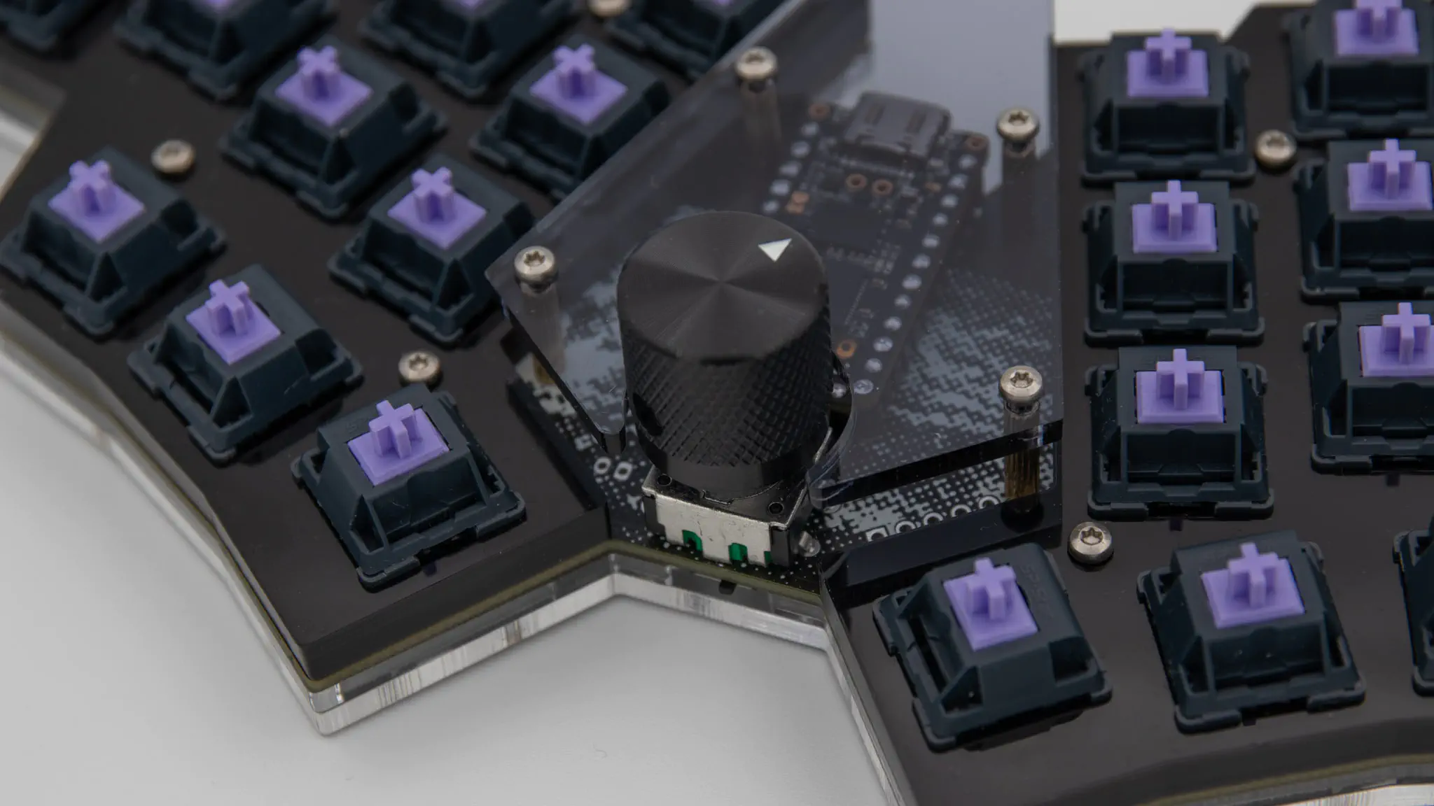
You also need to solder in your rotary encoder. You can find instructions for that here. On the Splaytoraid you need to clip one of the big pins, otherwise it will not fit!
optional
If you don’t want to go with MX style switches you can also ignore the switch plates and just solder in choc switches.
If you want you can solder in the RGB LEDs! Place the PCB in front of you, so that the side with the hotswap sockets on it is facing you. Solder in the LEDs now, facing your way! This is important because we use the LEDs as underglow LEDs. You can find instructions for that here.
You can also make this board bluetooth compatible. In order to use bluetooth, you have to solder in a battery connector.
Assembly
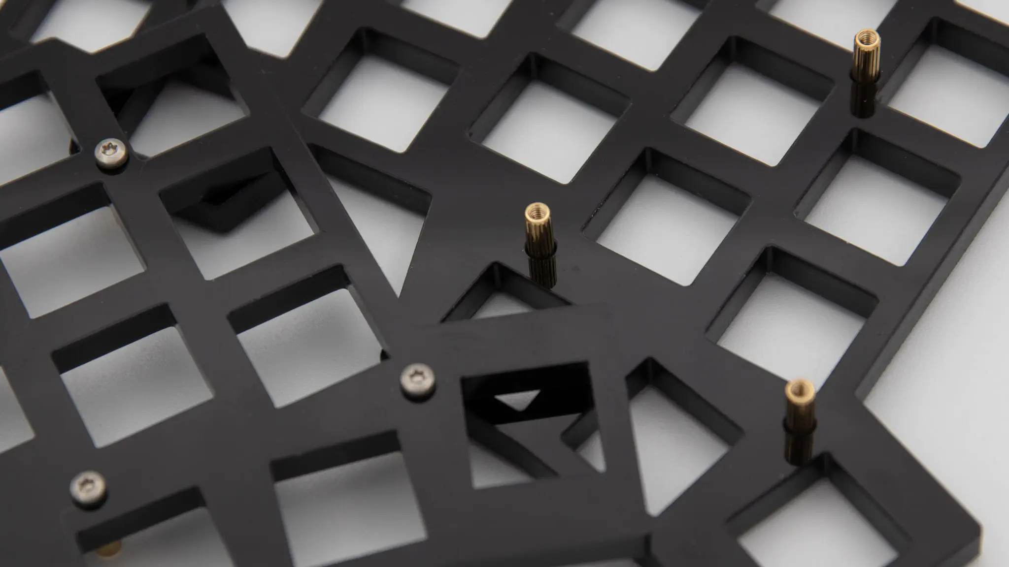
Go ahead and screw in the M2x12mm standoffs using M2x5mm screws.
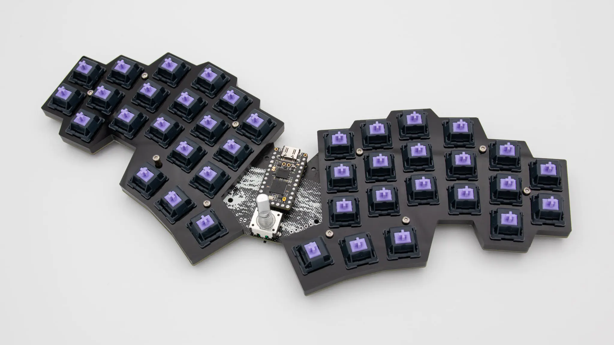
Put on your switch plates again. Check again, if you have removed the plastic film!
Push in your switches now. Be careful and hold your thumb against the hotswap sockets from the back so that they don’t break out.
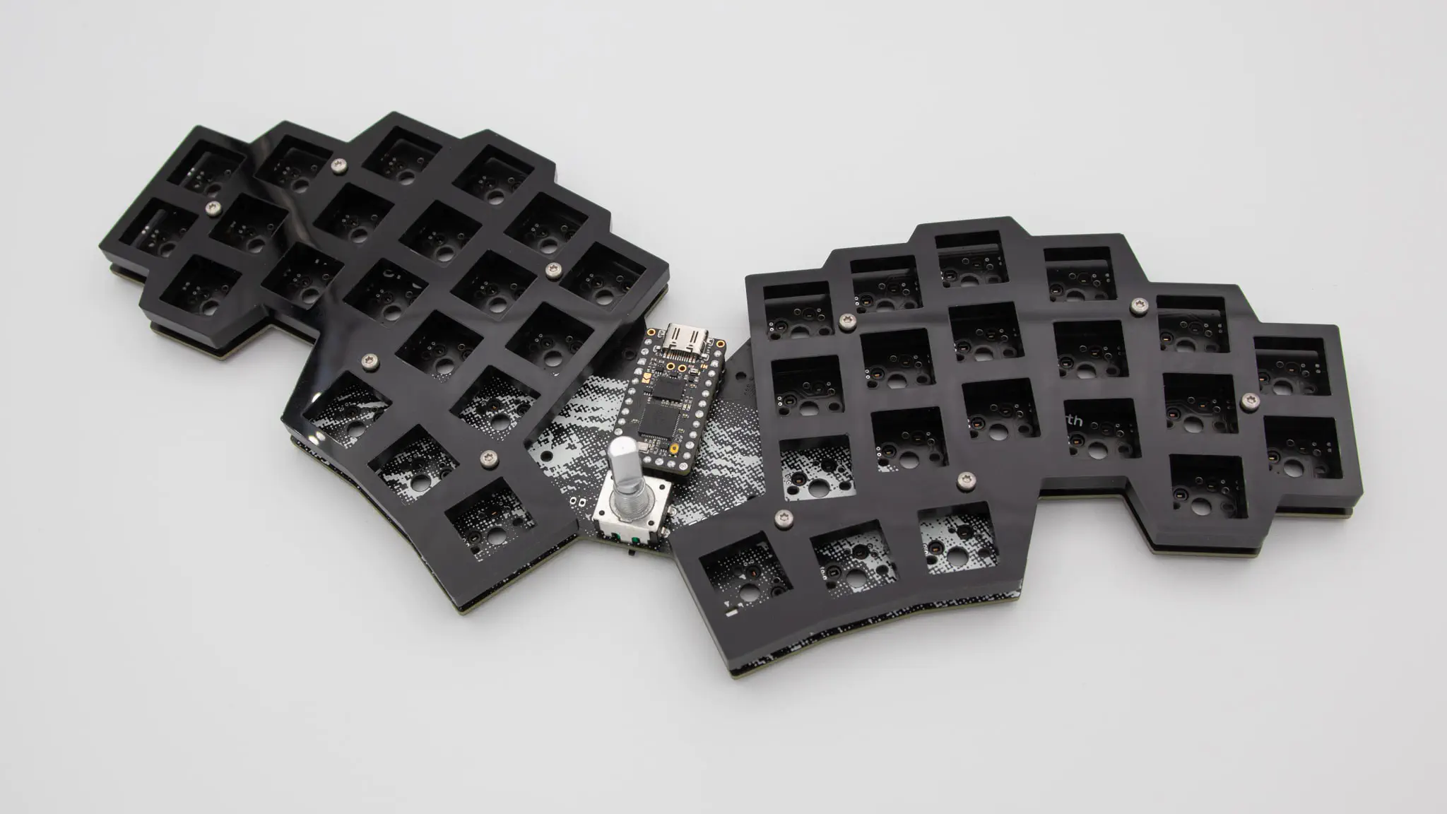
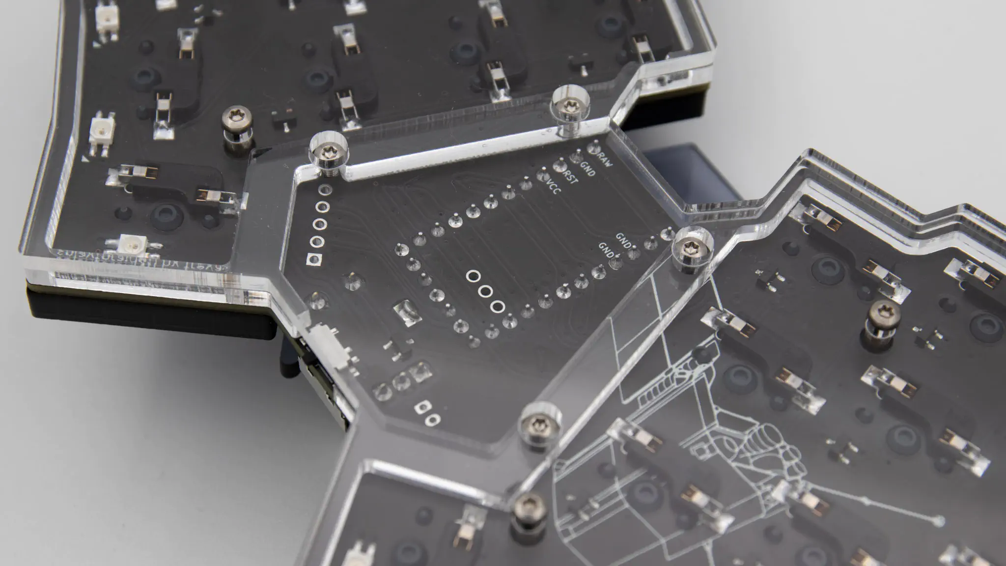
Turn the keyboard around and put on your two middle layers.
Be careful! They are not symetrical. The middle layer with the two cutouts on the right also goes to the right. You can easily check this, if your middle layer leaves room for your hotswap sockets.
Now put on your bottom layer.
Screw in the bottom layer with the short M2x5mm screws.
Take out the acrylic cover and screw in the 4 M2x11mm standoffs using the remaining M2x5mm screws.
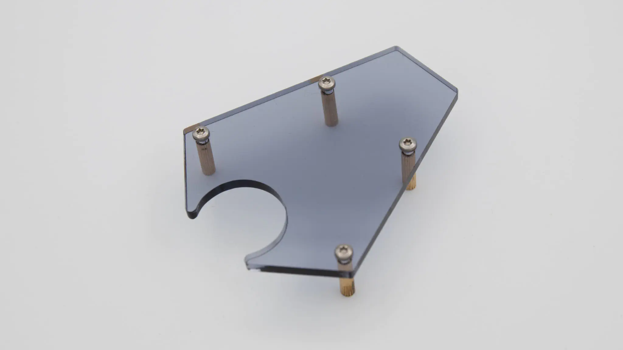
Place it on top of the PCB.
Screw it in from the bottom with the long M2x11mm screws.
Put on your encoder knob and tighten it.
Put on your rubber feet.
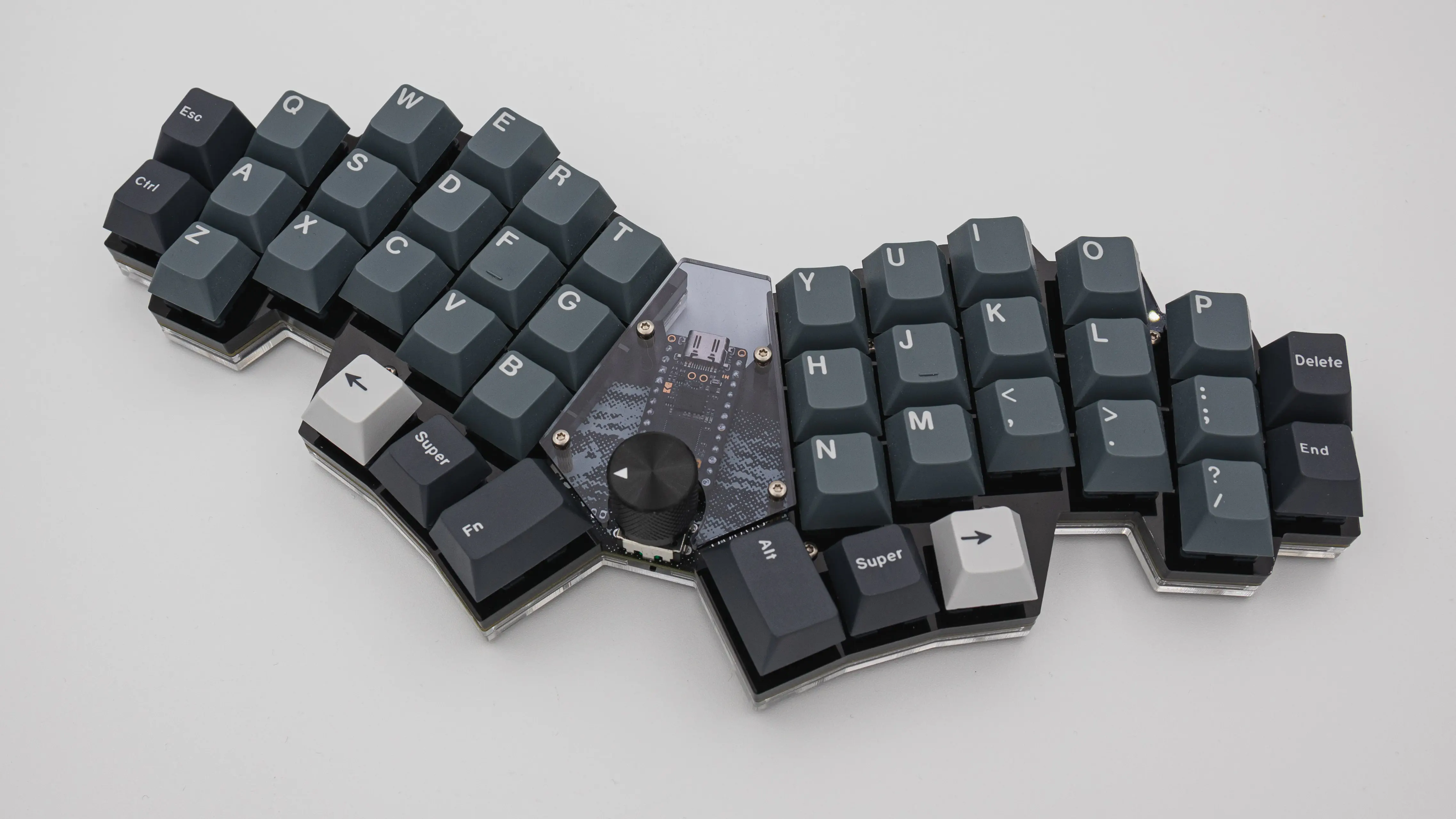
Now you can put on your Keycaps and you are done!