Assembly
Soldering
Depending on if you bought a wireless or wired version there will be different things that you need to solder. We’ll start with the steps that are the same for both versions, then cover the differences.
Both Versions
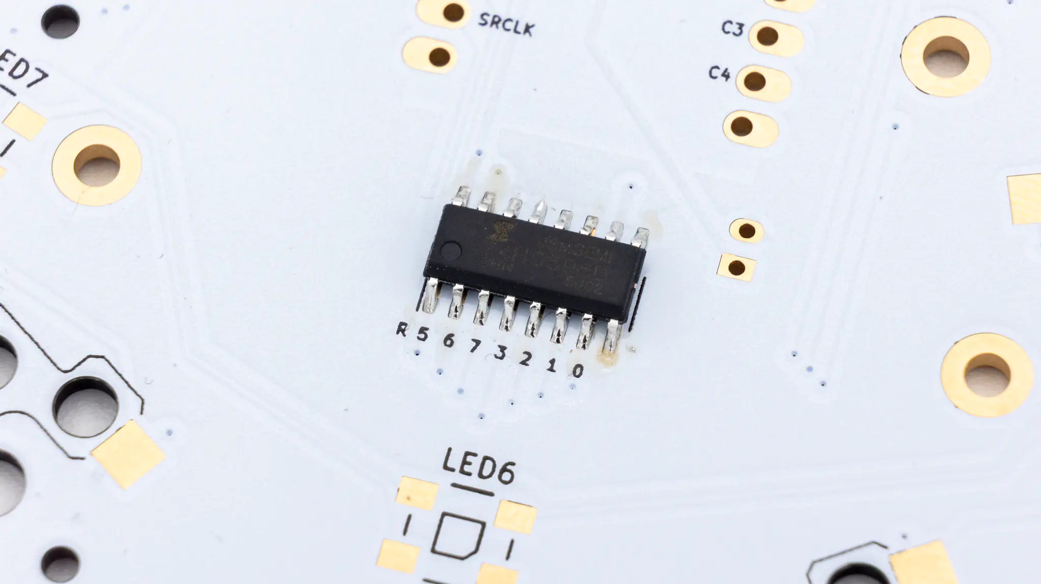
Shift Register
The first component to solder is the shift register. This component has tiny pins and is quite difficult to get right. The dot on the shift register should align with the long line and R on the PCB. If you have not soldered this kind of component before we recommend looking up drag soldering and learning how to do that.
Reset Button
Solder the reset button next.
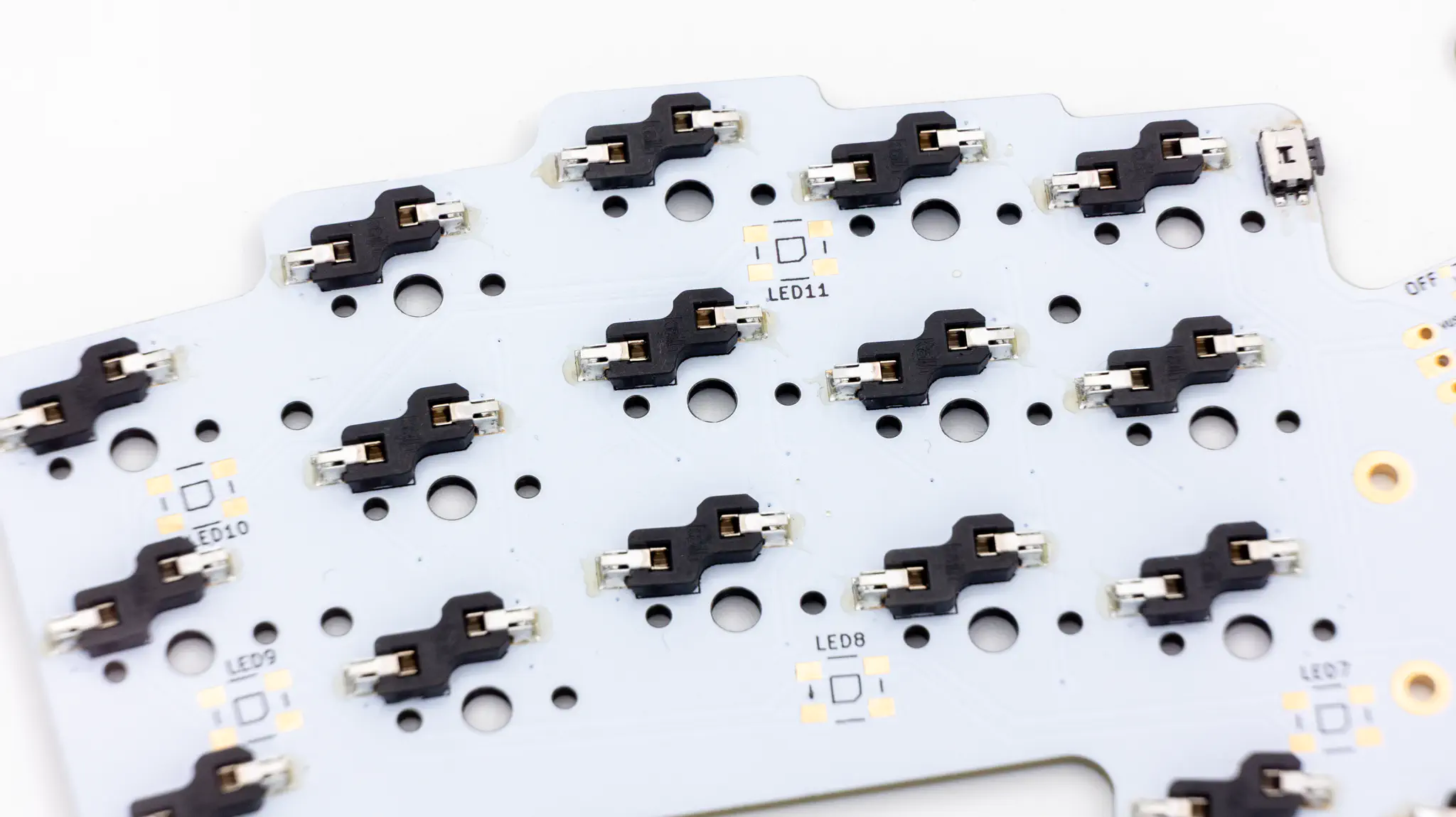
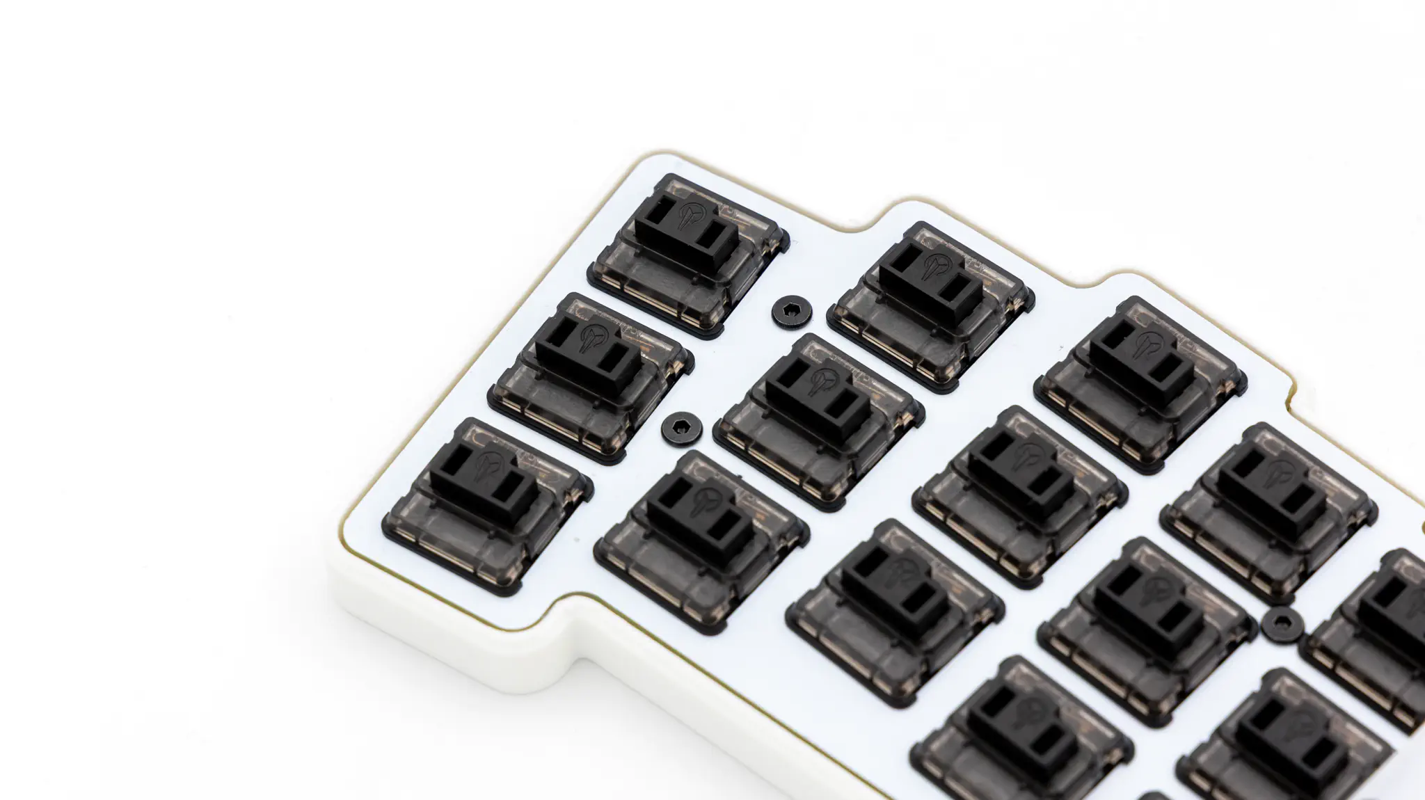
HotSwap Sockets
Solder the HotSwap sockets next. You can find instructions for that here.
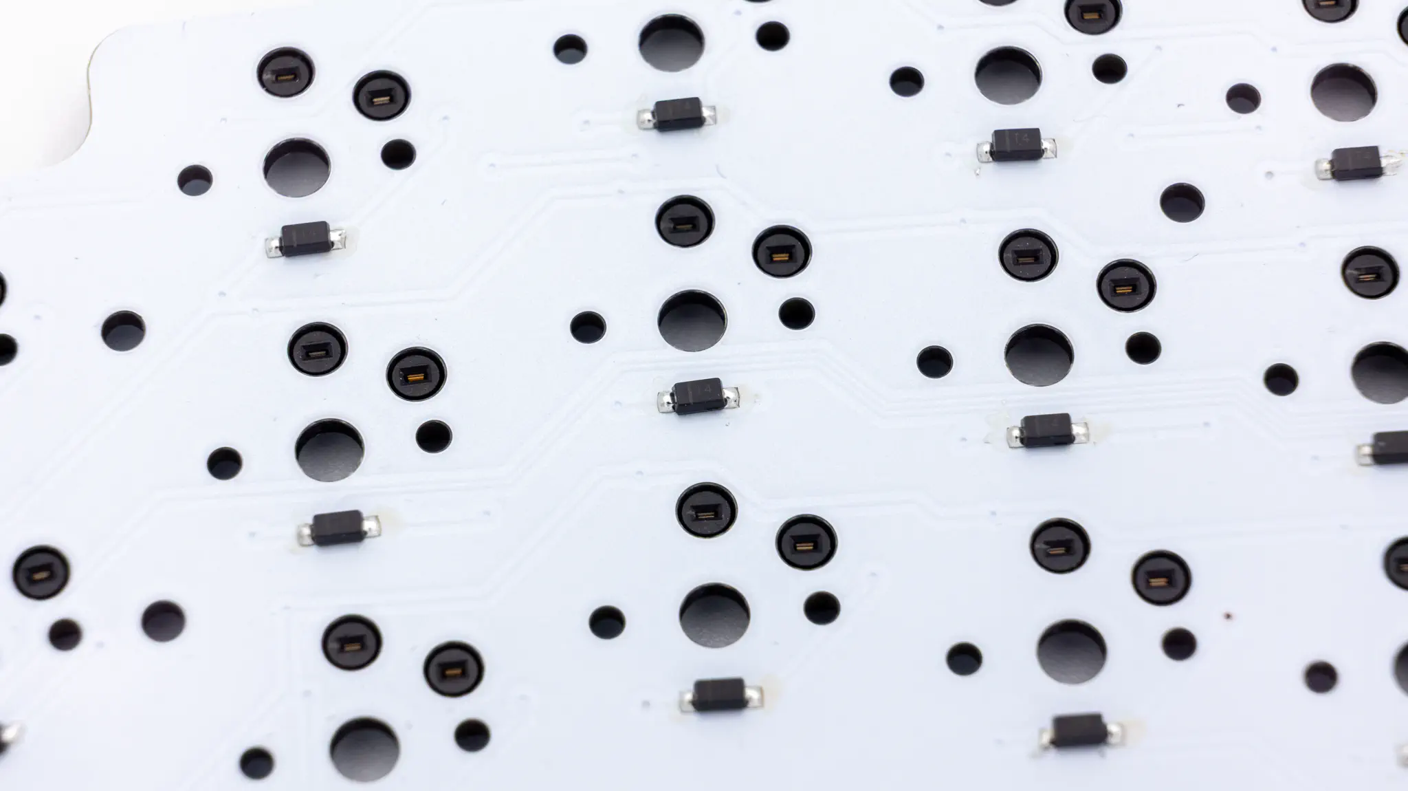
Diodes
Solder the diodes next. Read through here if you have not done this before.
Pogo Pin
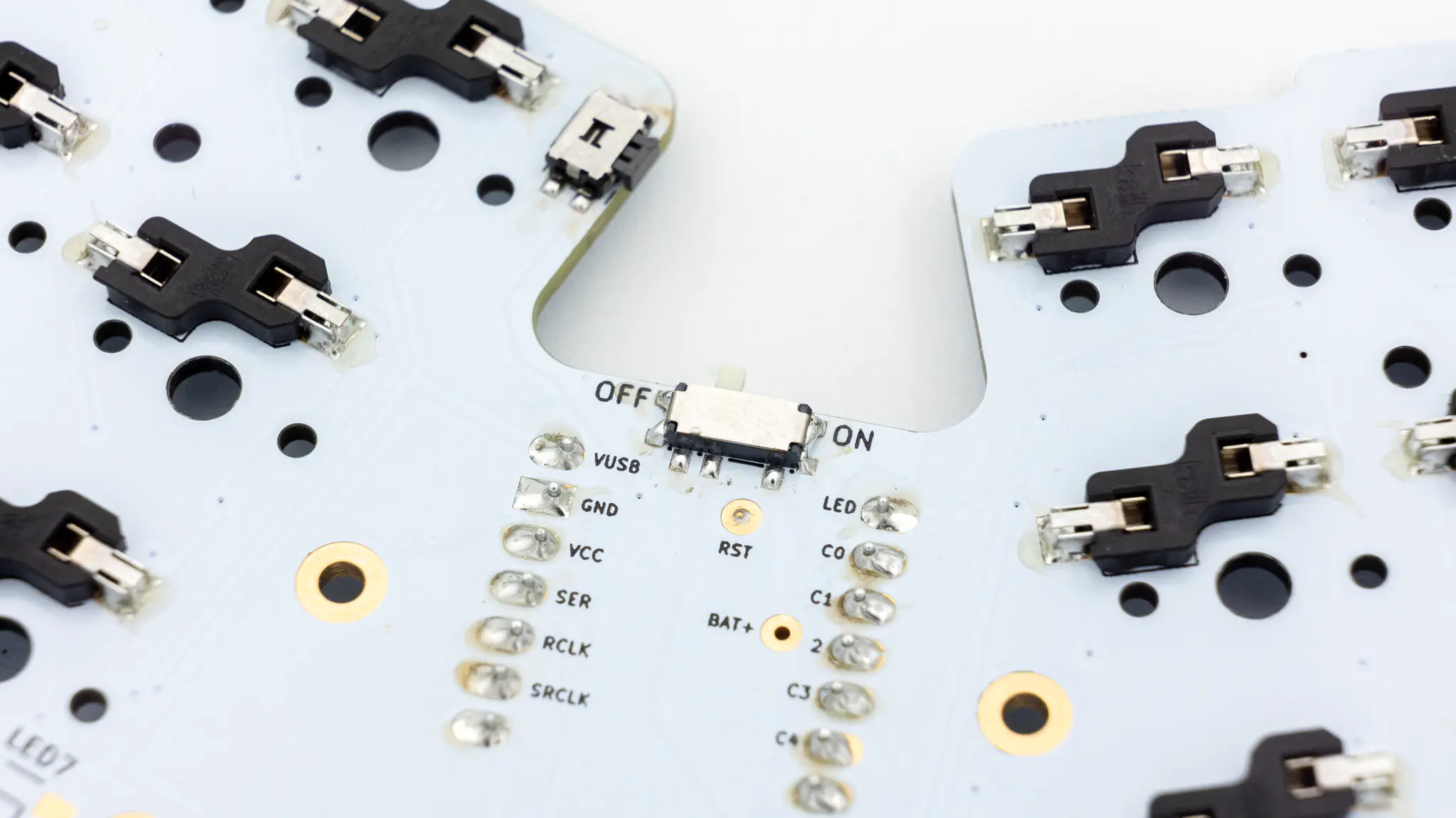
Solder the top pogo pin that is marked as RST on the back next. Stick it through the PCB and add solder to it. You can add solder onto both sides of the PCB, choose whichever works best for you. Just make sure that the top part can still move.
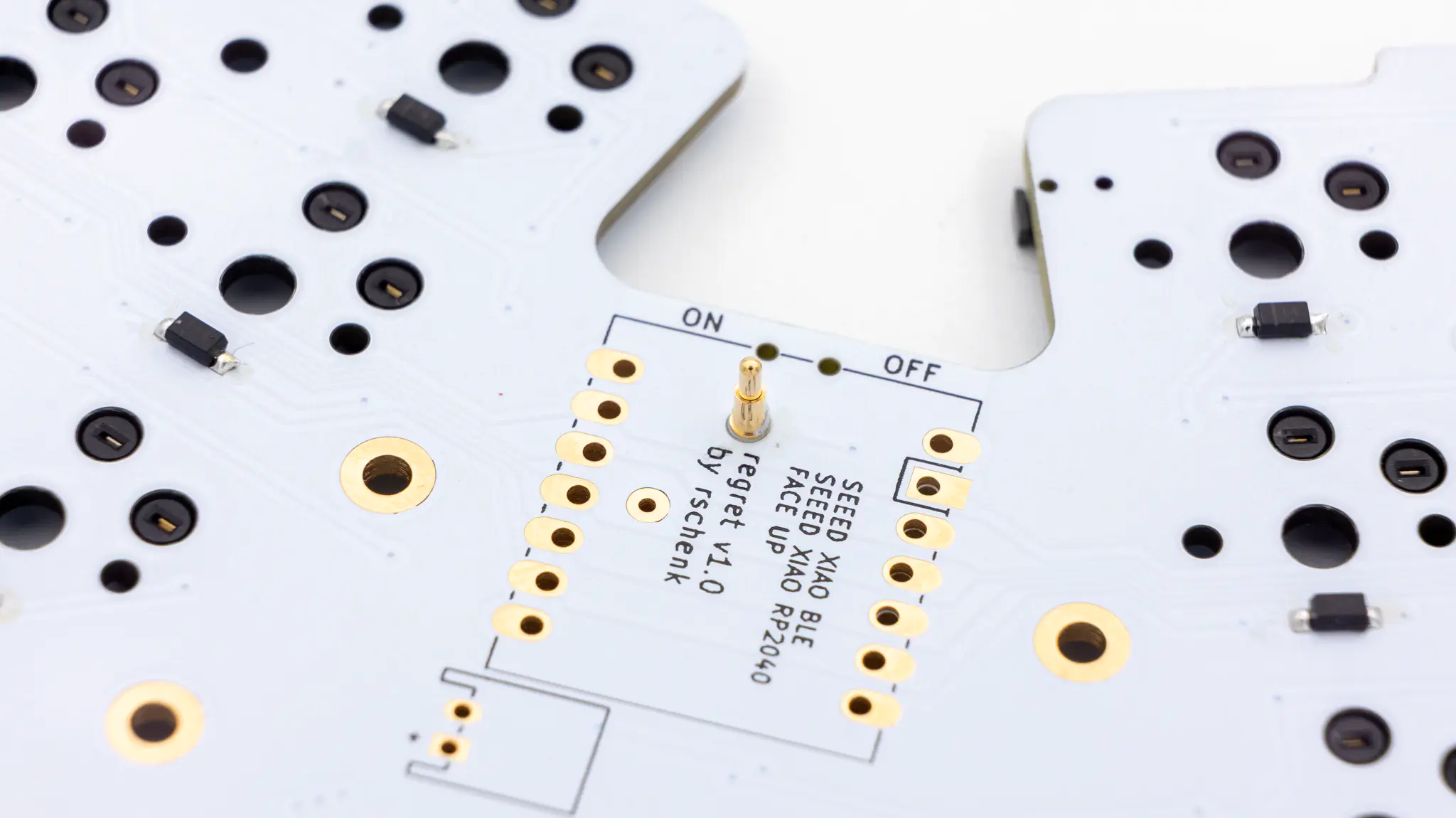
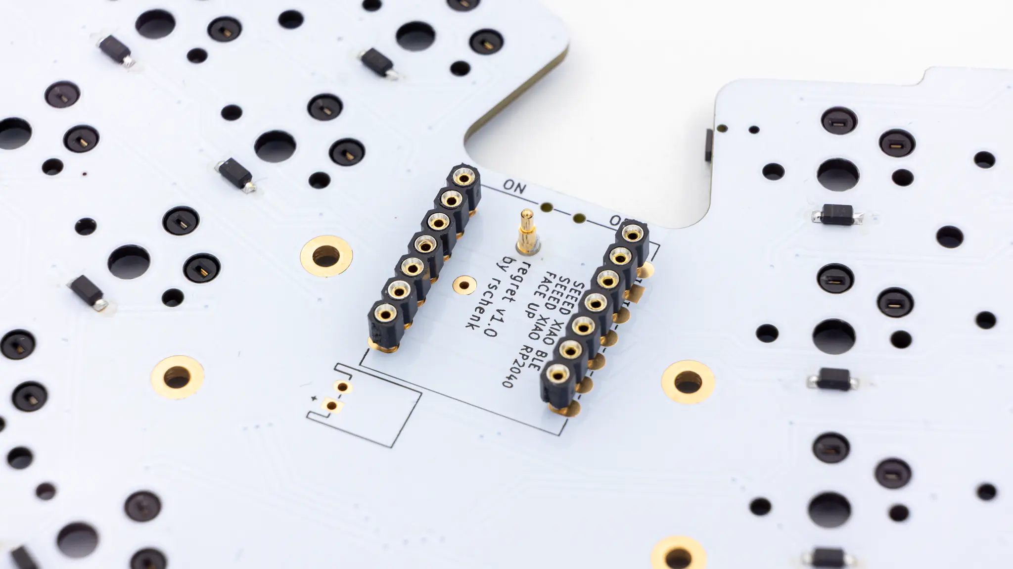
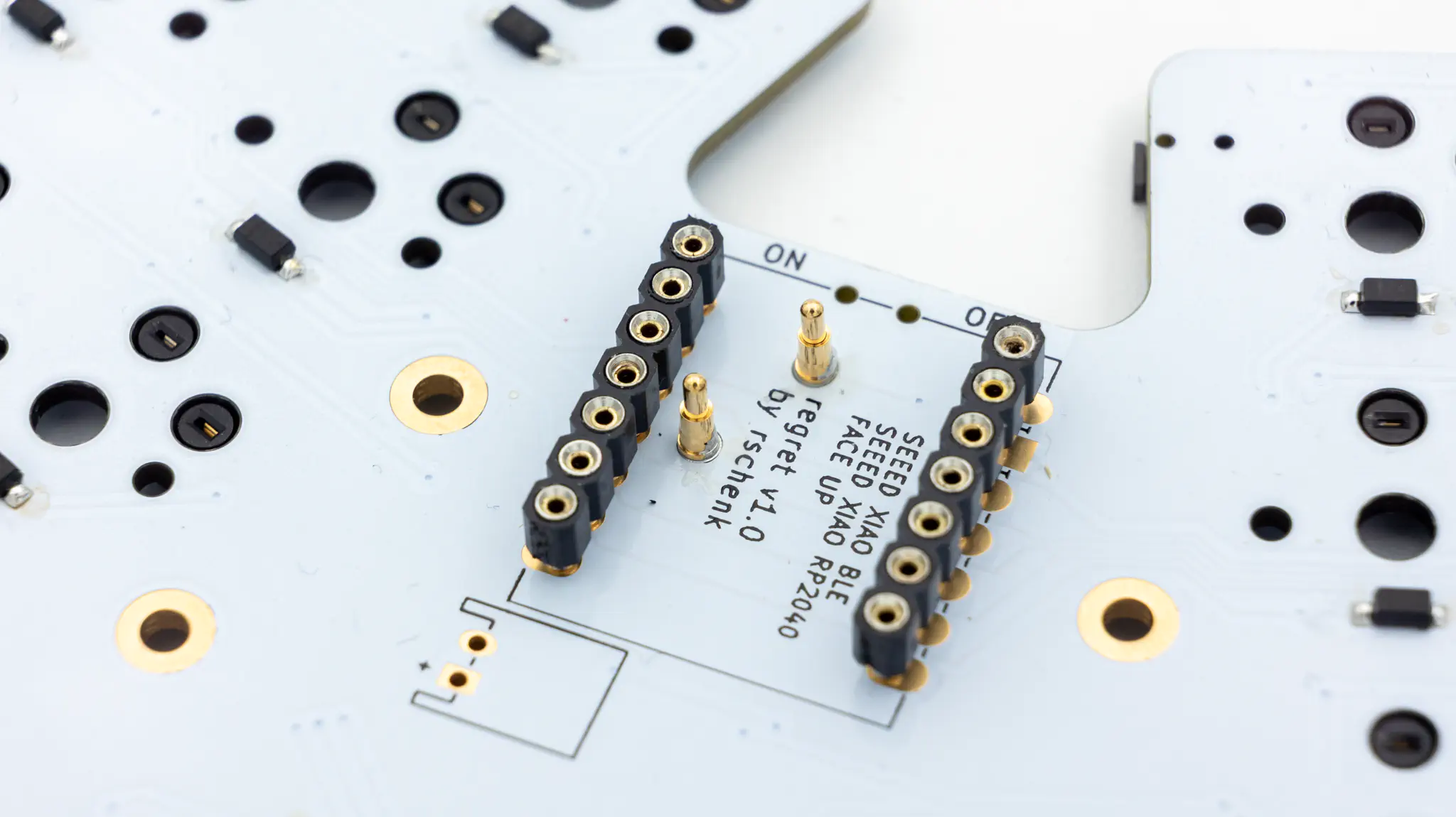
Controller Standoffs
Next solder the standoffs for your controller. You need to use IC sockets with MillMax pins for this board. Read through here if you have not done that before.
Please skip to this part now if you are building a wireless Re-gret.
Please skip to this part now if you are building a wired Re-gret.
Wired
All of the steps in this paragraph need to be done when assembling the wired variant of the Re-gret.
Controller
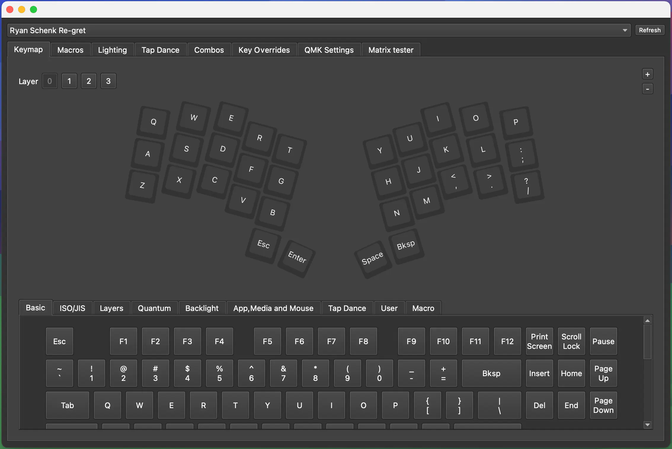
Before soldering the controller onto the PCB you should check if the correct firmware is on there.
You can find the VIAL firmware here. And instructions on how to flash a controller here.
Plug in your controller now and see if it pops up in VIAL.
If your controller is working, you can solder it in. Instructions on how to do that can be found here.
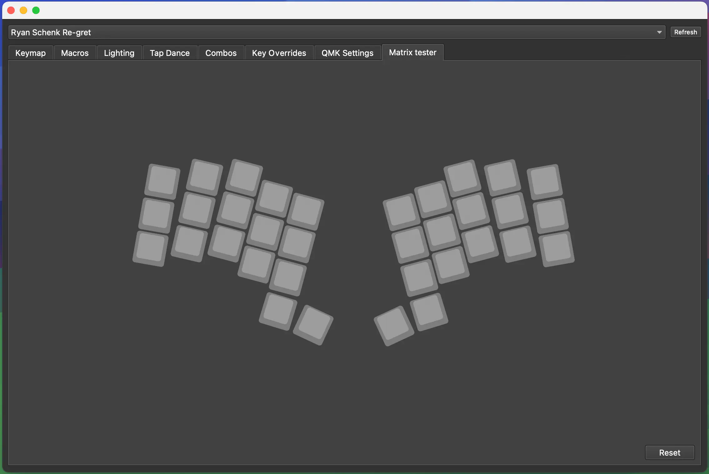
When you have your controller soldered in, it is good practice to do a matrix test with some tweezers.
You can now skip to the final assembly to continue.
Wireless
All of the steps in this paragraph need to be done when assembling the wireless variant of the Re-gret.
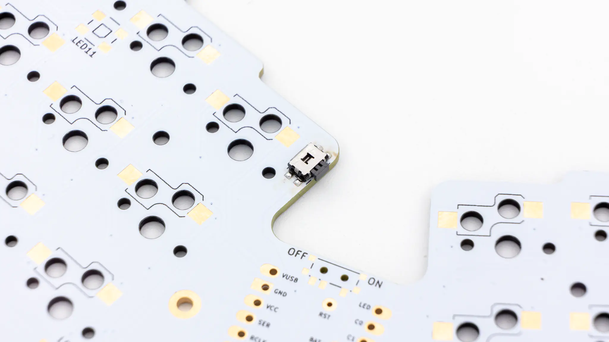
Slide Switch
You will need to solder in the slide switch to be able to power the keyboard on or off. The switch is located on the back of the PCB.
Pogo Pin
To get power to the controller you need to solder the other pogo pin as well.
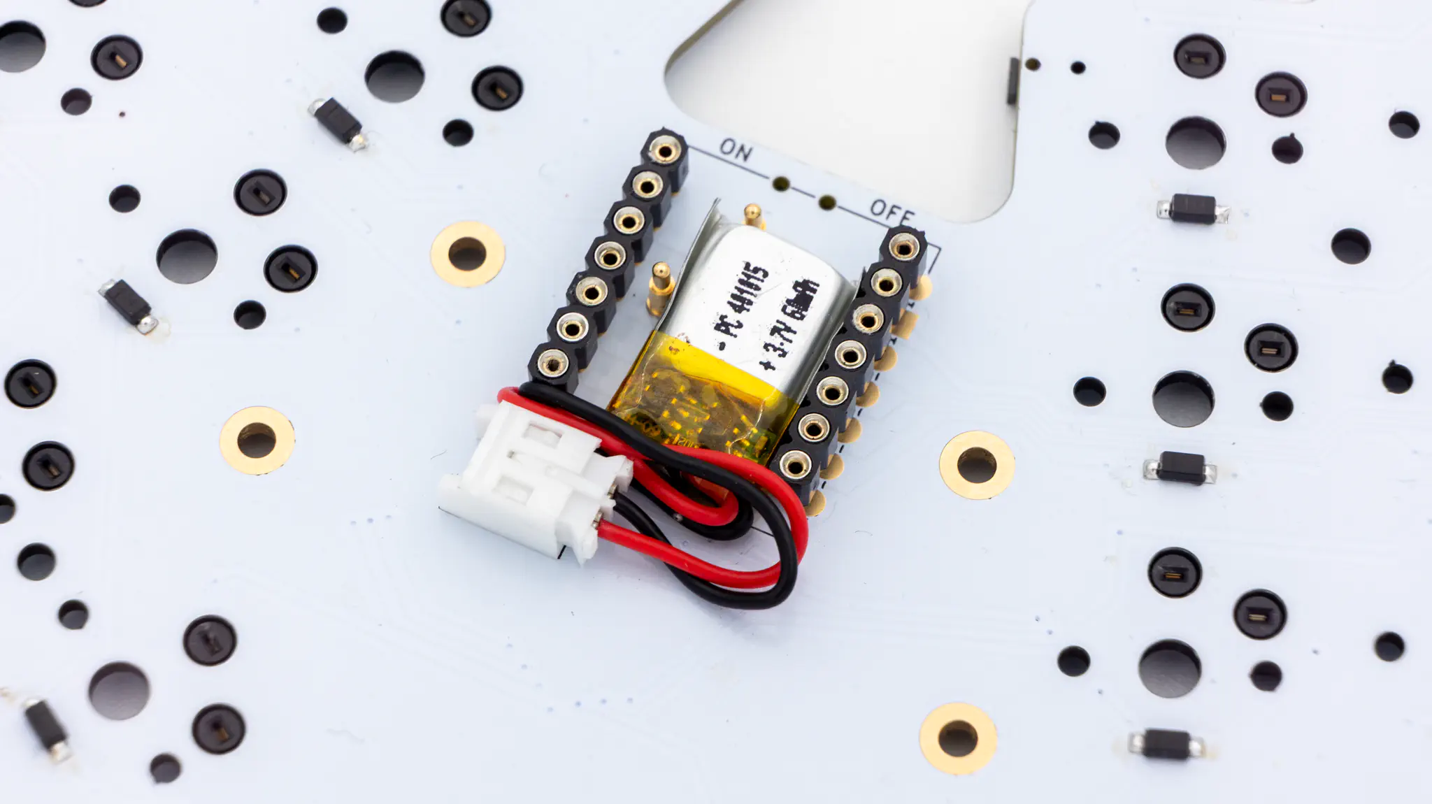
Battery Connector
Solder the battery connector to the front of the PCB. After you have soldered the connector you can plug in the battery and tuck it into the space underneath the controller.
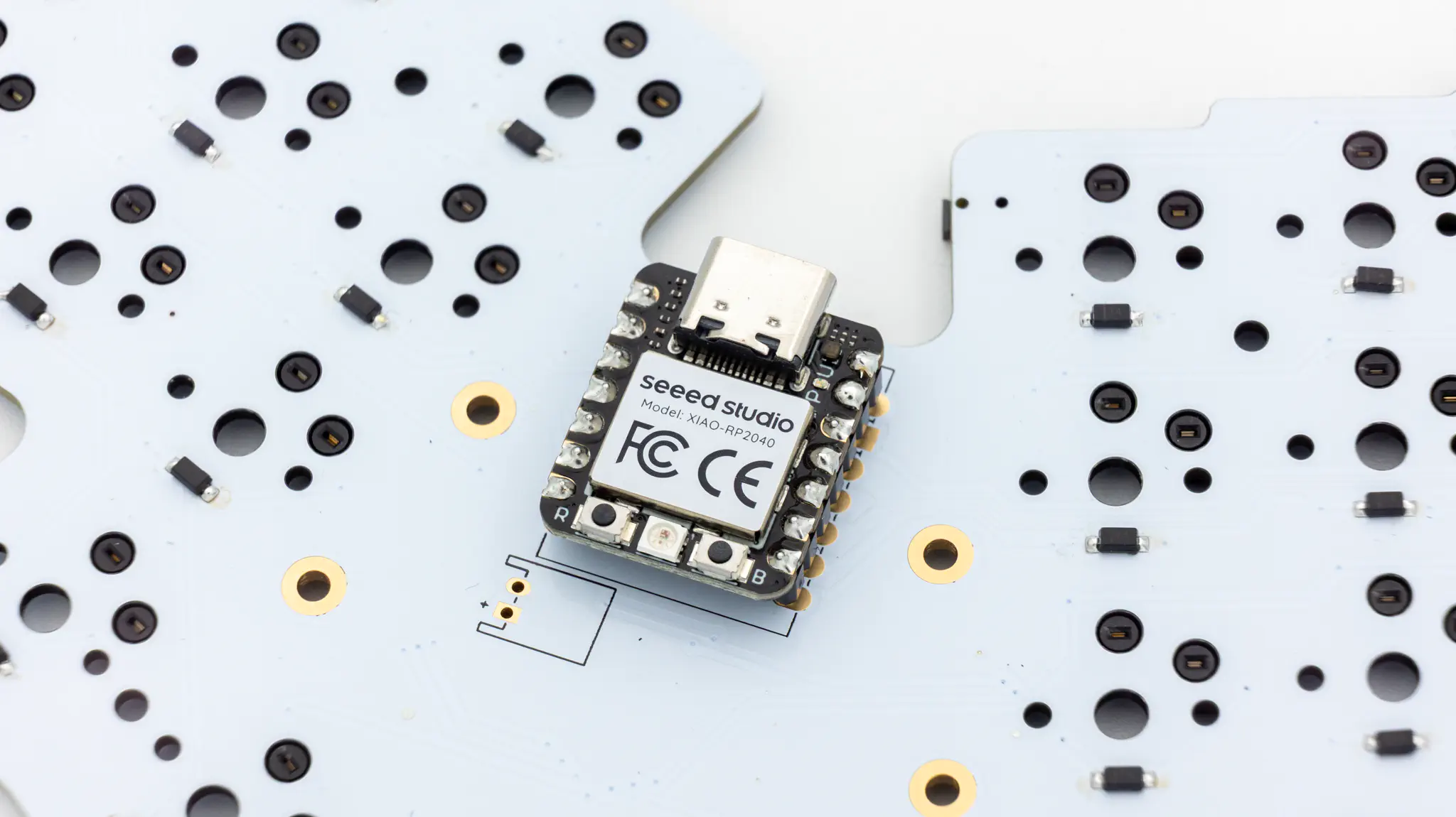
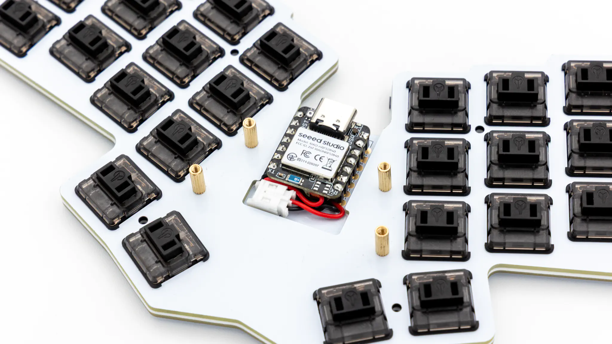
Controller
Before soldering the controller onto the PCB you should check if the correct firmware is on there.
The board comes with a precompiled zmk firmware found here, which is based on the official Re-gret ZMK module. You’ll have to set up a ZMK user repo to modify your keymap. Intructions on how to do that are available here. After that configure the Re-gret ZMK module following this. Instructions on how to flash a controller are available here.
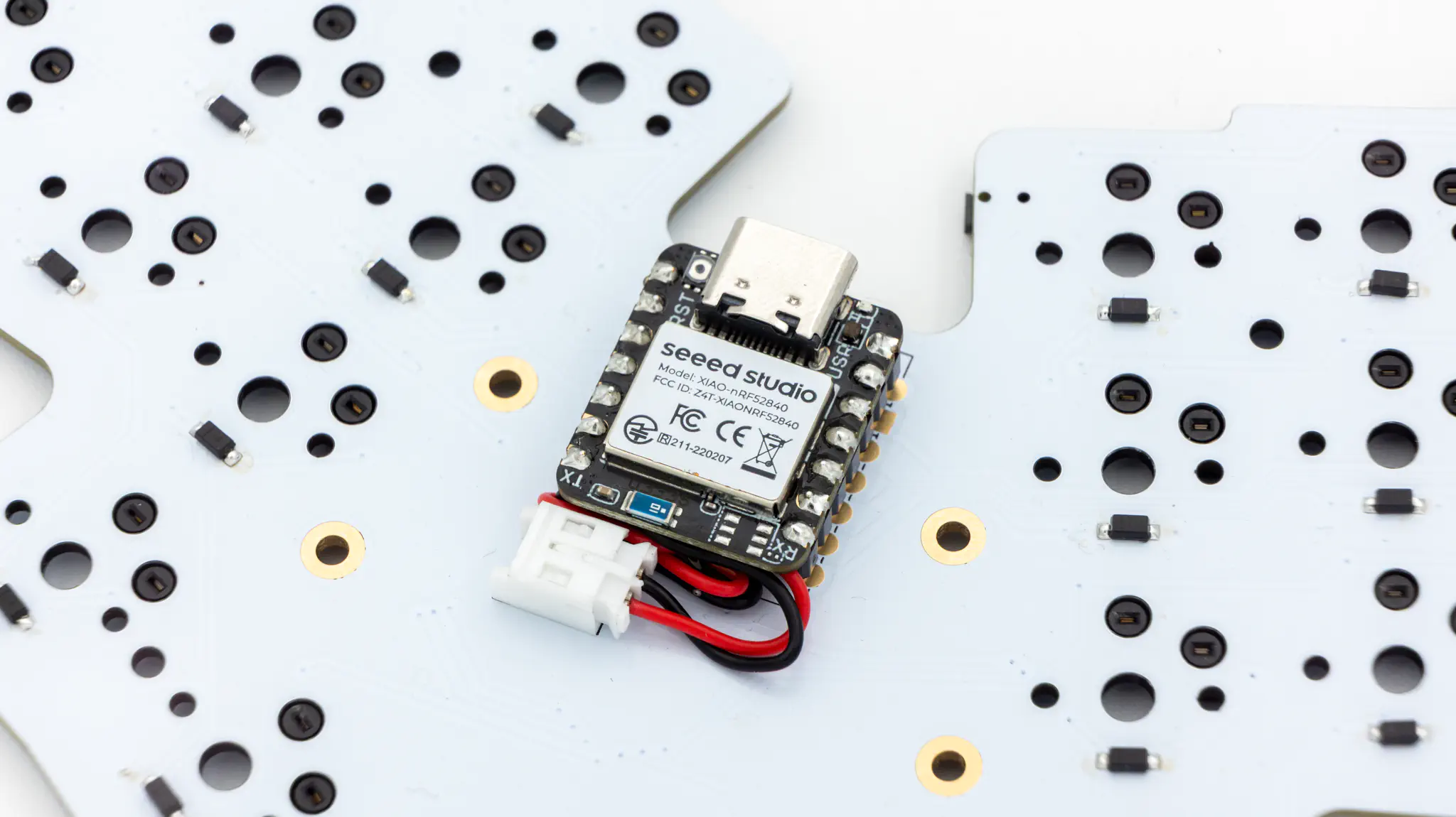
Solder the controller to the headers now using the MillMax pins. Instructions on how to do that can be found here. When you have the PCB in front of you, the USB port should go to the top of the PCB. You should see the metal shield of the controller, when it is sitting on the PCB.
You can now continue reading the final assembly to proceed.
Final Assembly
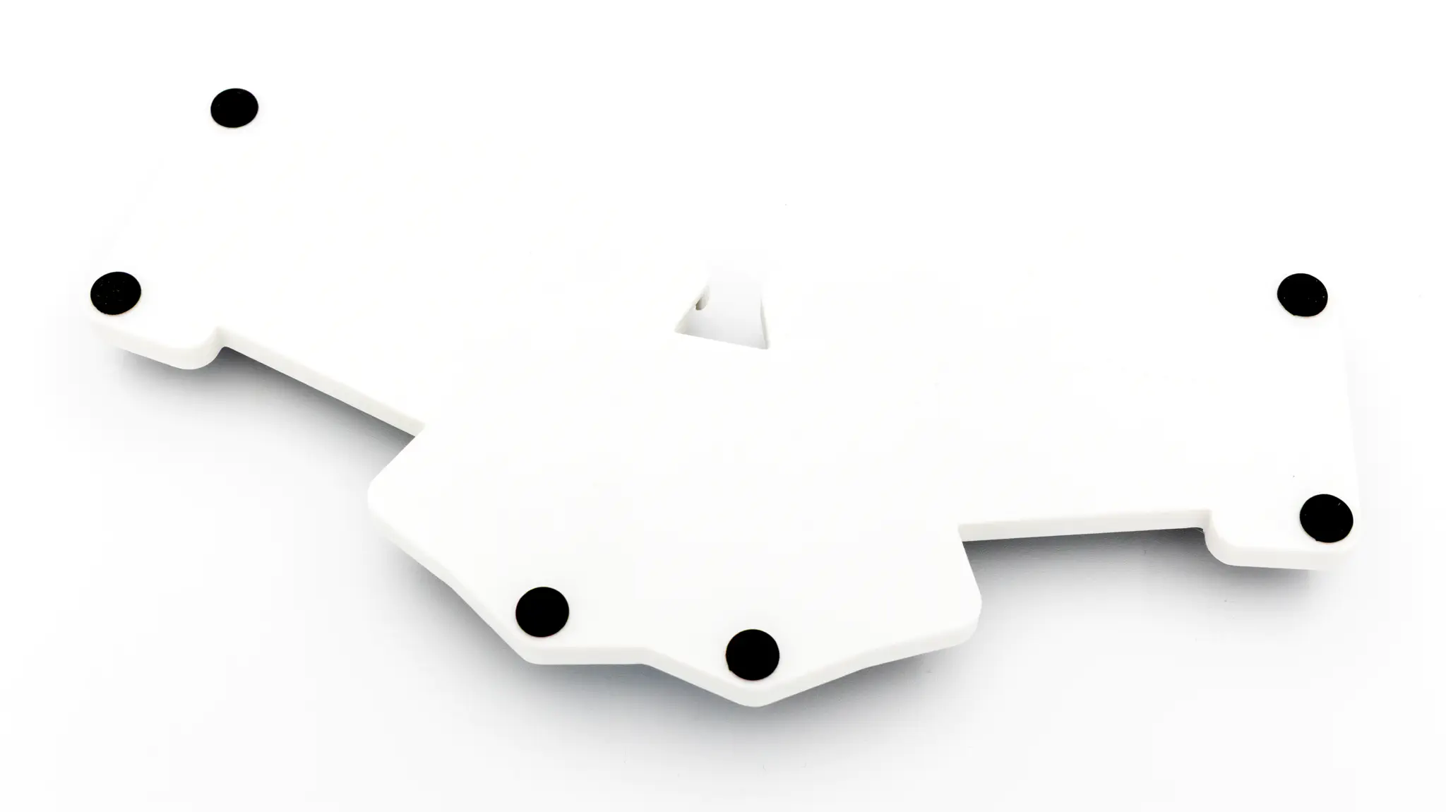
Start by placing the 3D printed spacer on the PCB and then the FR4 plate.
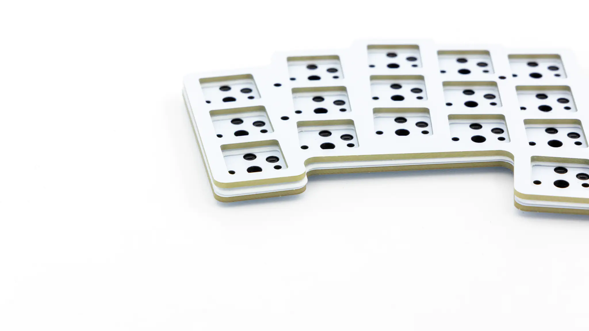
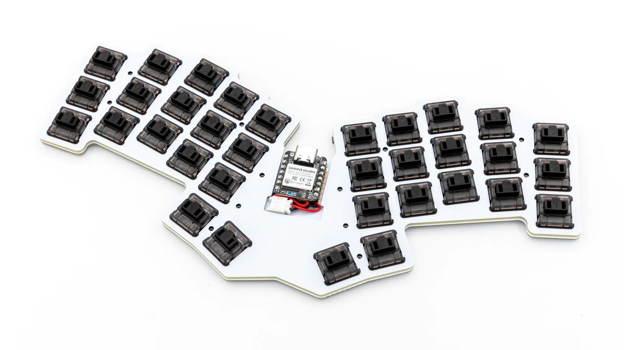
Insert the switches that you want to use into the cutouts.
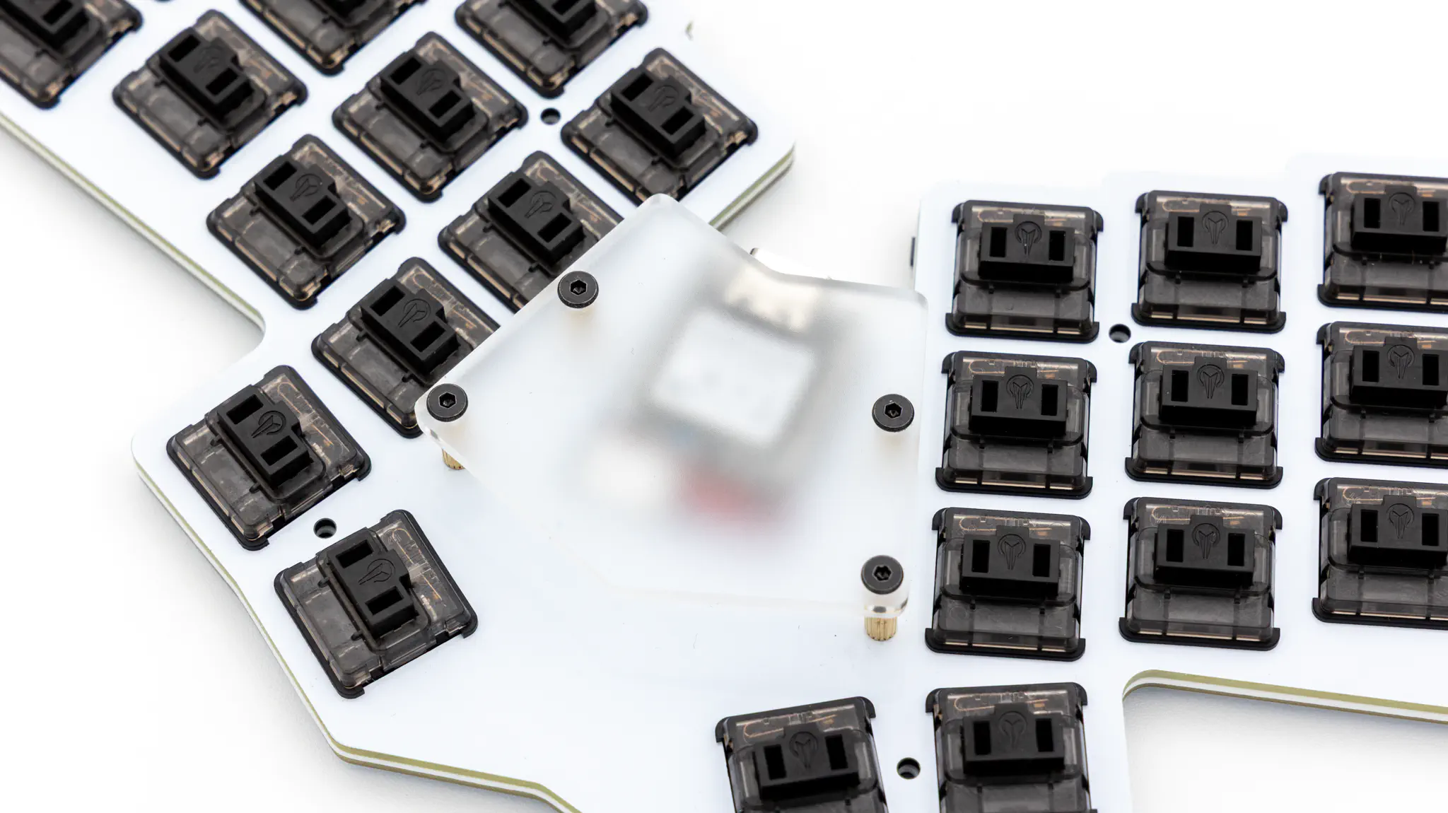
Screw the 4 standoffs into the stack from the bottom.
Remove the protective film of the acrylic cover, put it on the standoffs and screw it in from the top.
Place the stack into the 3D printed case and screw it in using 8 screws.
Put the rubber feet onto the 3d printed case. We provide 6 feet which you can place wherever you want on the bottom side.
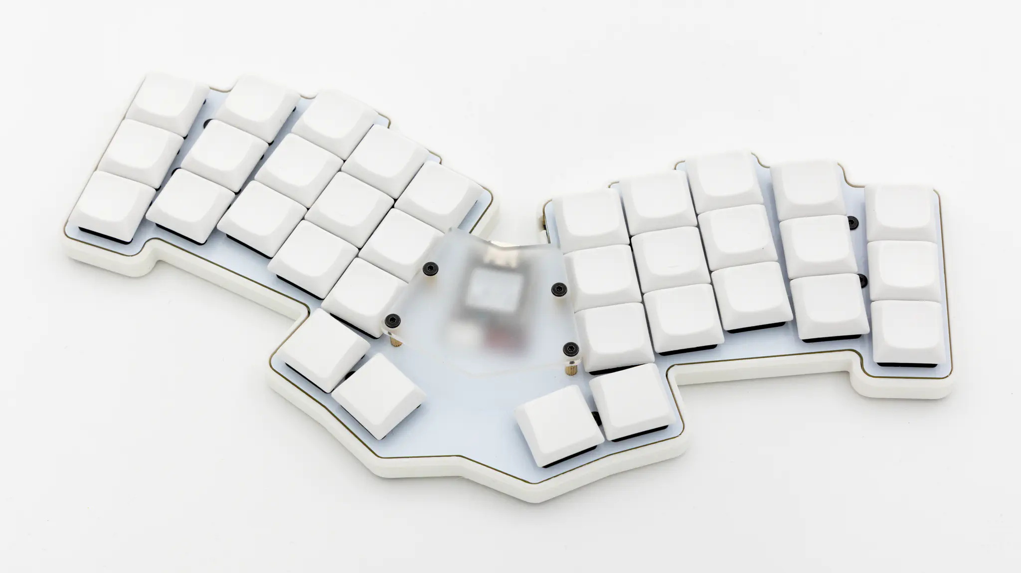
Put on your preferred keycaps and your Re-gret is done!