Title here
Summary here
There are a few things you absolutely need to solder and a few which are optional. If you do not have experience with soldering, please refer to this Quick Start guide.
All of the steps below need to be done on the right and left half of the board.
Note
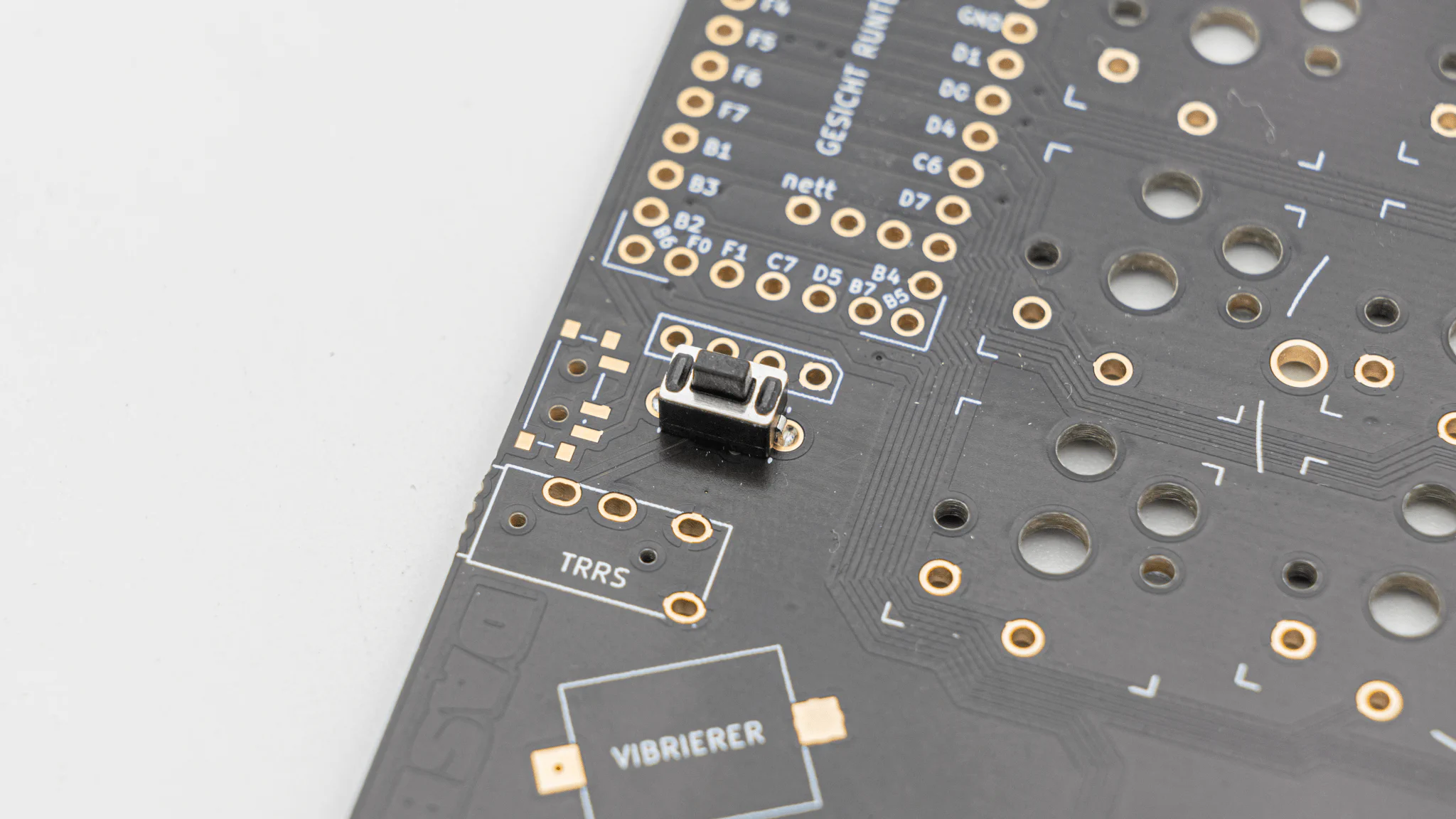
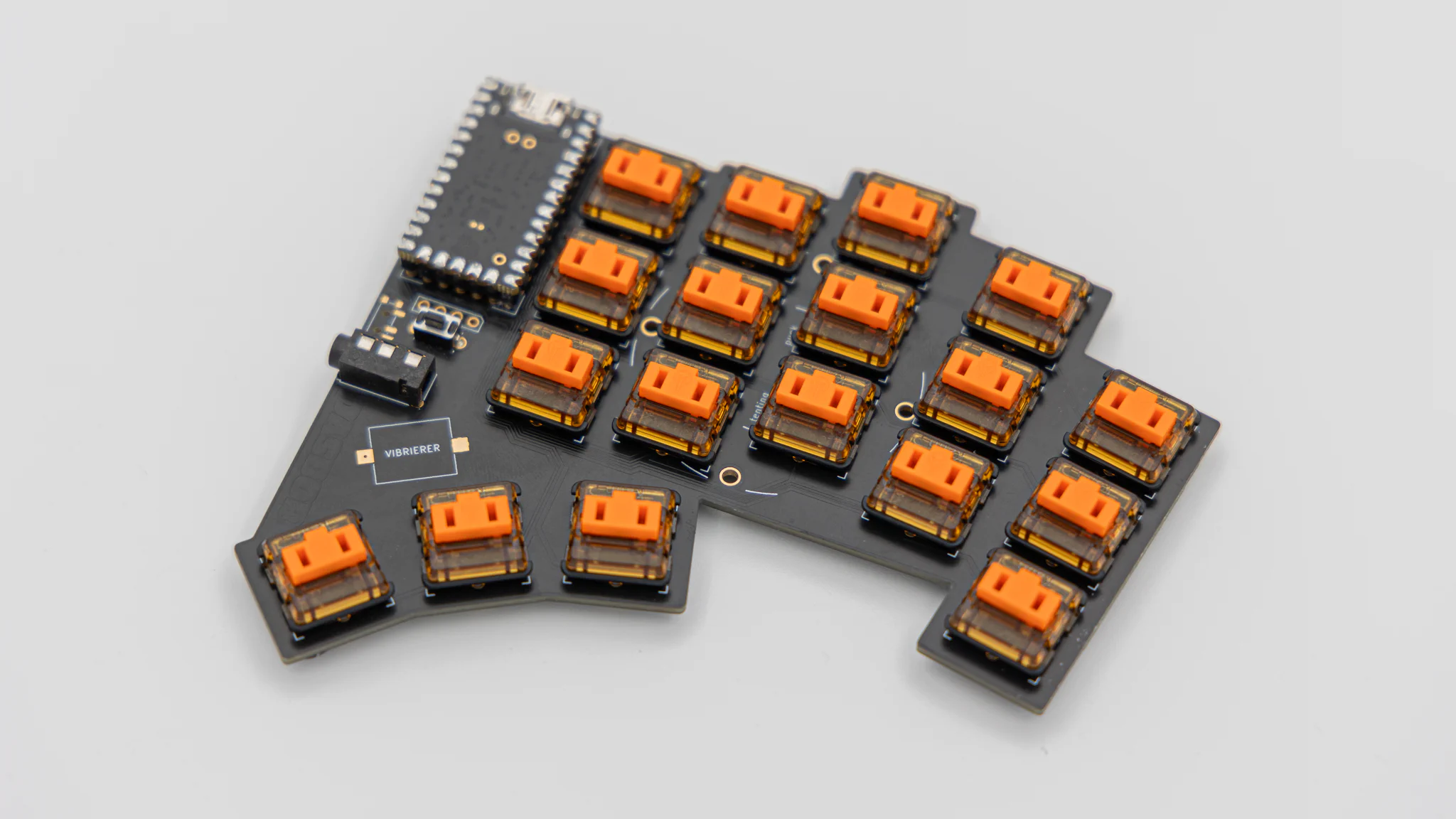
The reset buttons, trrs jacks and controllers all go on the top side of the keyboard. That is the side, where the HotSwap sockets are NOT on.
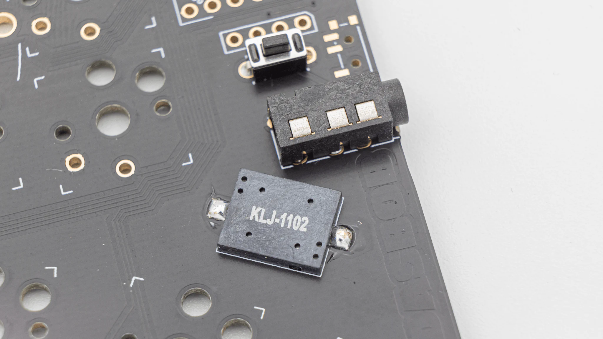
Solder on the reset buttons.
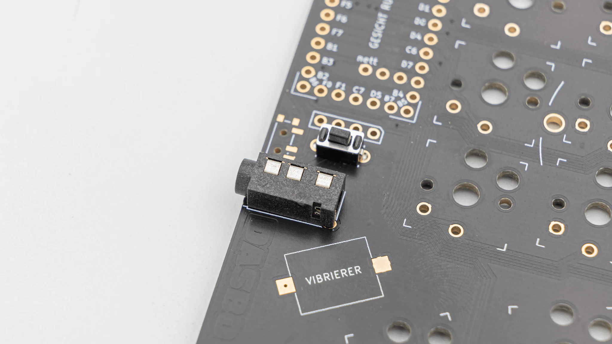
Solder on the TRRS Jacks.
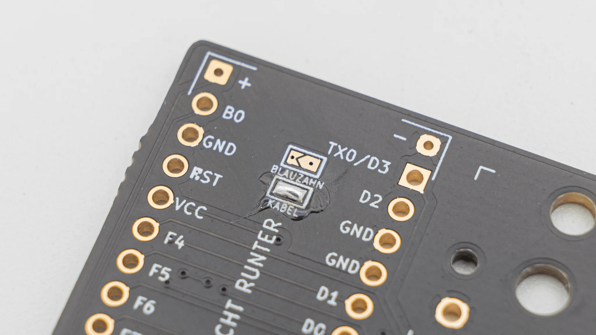
There is a jumper located below the controller. You will have to solder the wired or bluetooth jumper depending if you use a wired or wireless microcontroller.
Before soldering the controllers onto the PCB we should get your controller flashed.
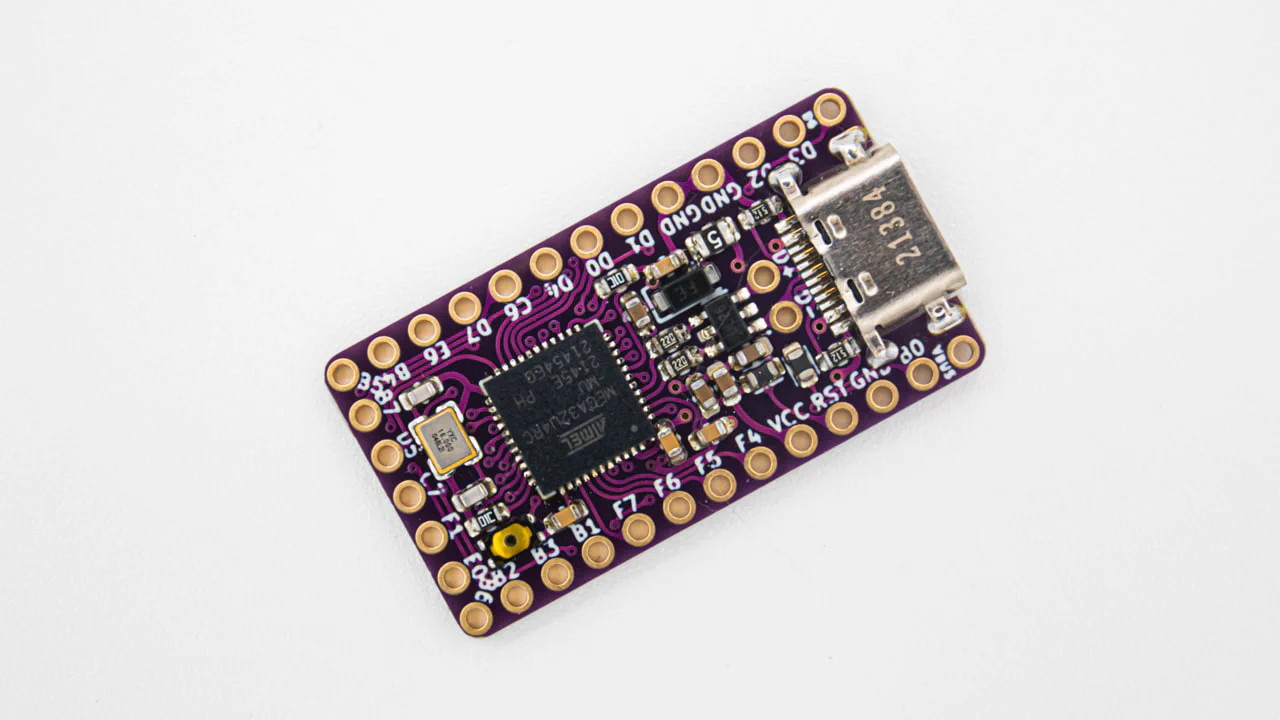
You can find the firmware here. And instructions on how to flash a controller
here.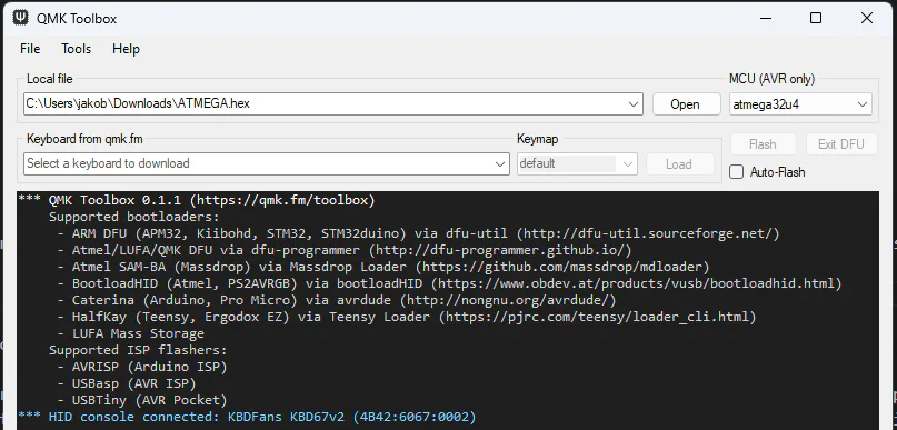
Plug in your controller now and see if it pops up in
VIAL.
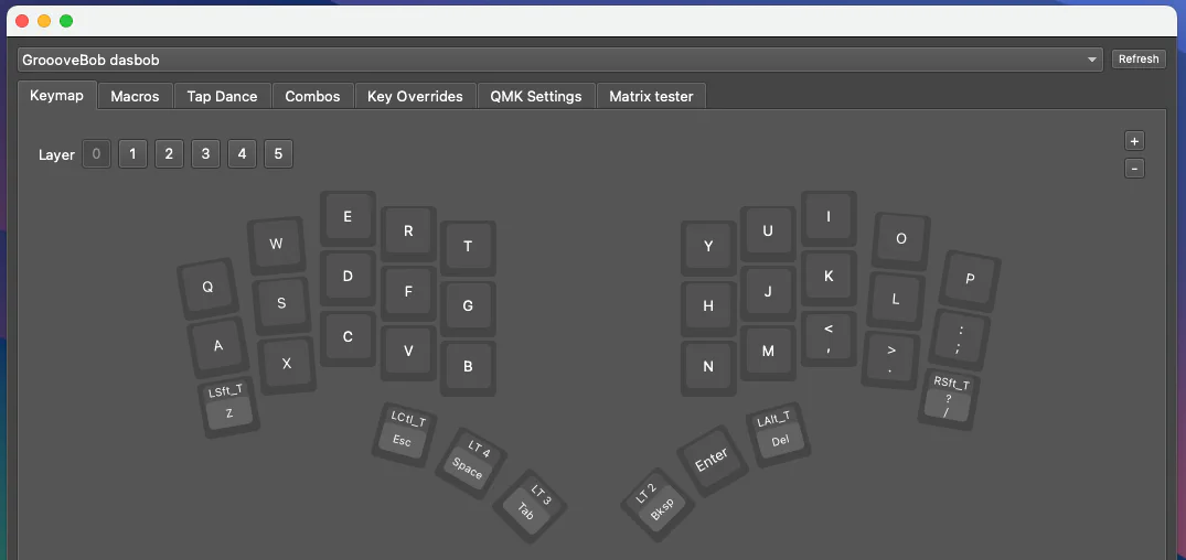
If it does you have successfully flashed your controller.
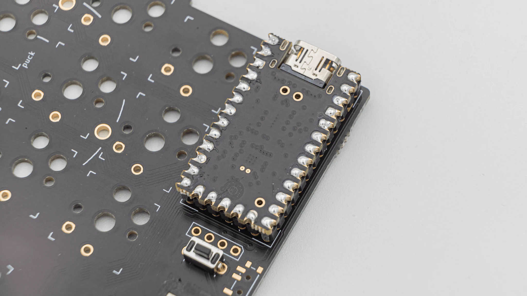
If your controller is working, you can solder it in. Instructions on how to do that can be found
here. When you have the PCB in front of you, the USB port should go to the top of the PCB. You should not see the components of the micro controller, when it is sitting in the PCB.
Note
The top two through holes, labelled + and -, are for batteries. If you are using your DASBOB with a wired connection, please do not solder these to the controller.
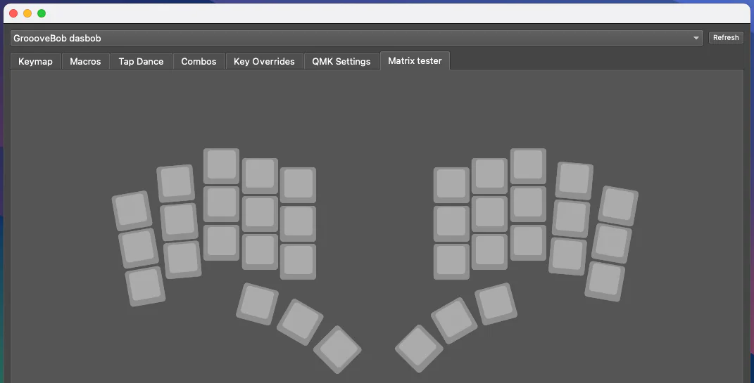
When you have your controller soldered in, it is good practice to do a
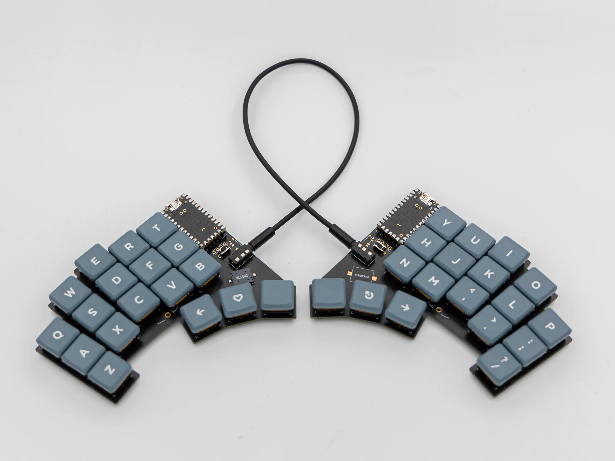
matrix test. Since DASBOB is a split keyboard, you need to plug in the two halves together using the TRRS Cable.
Note
Do not hotplug the TRRS Cable, when your controllers are plugged into your PC. This can and will damage the board. Always unplug the keyboard from the PC, before plugging the TRRS Cable in.
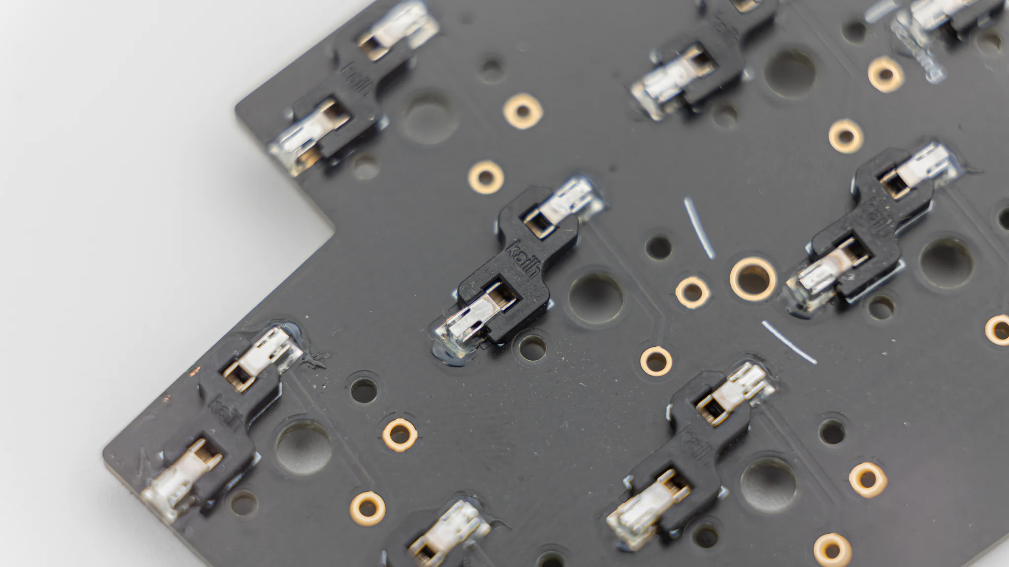
You can solder in HotSwap Sockets. You can find instructions for that here.
Note
If you decide to not solder in the hot swap sockets, you will need to solder in the switches later!
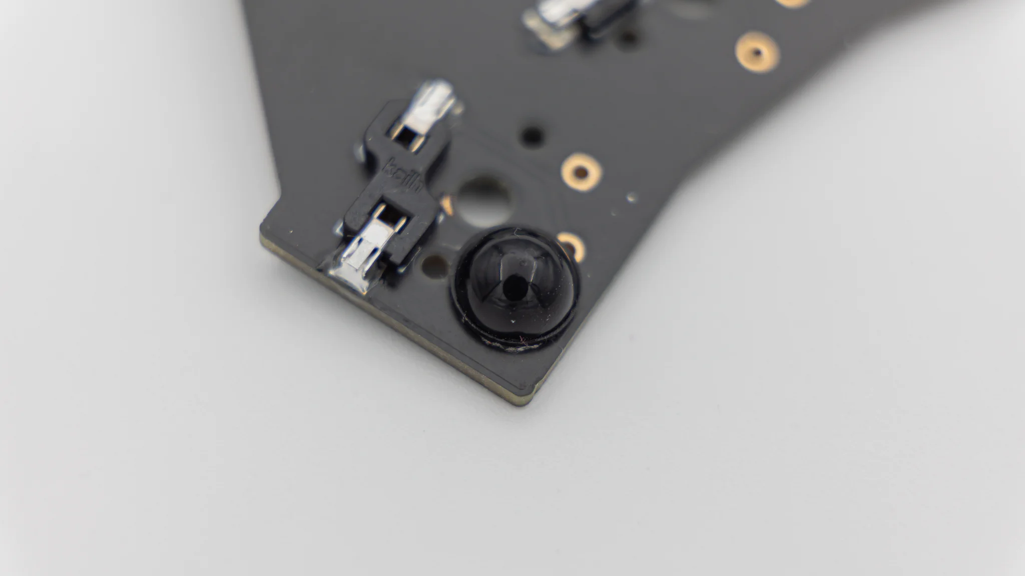
The PCB also supports a buzzer. You can find information on speakers here. The speaker is located underneath the controllers. There are two buzzer footprints, but only one buzzer will work at a time.
Note
With the default firmware that we provide, you need to solder the buzzer onto the left side!
This is everything you need to solder for now!
Start by putting on the rubber feet. We provide 4 feet per side which you can place wherever you want.
After that push or solder in the switches.
As a last step put on your keycaps.
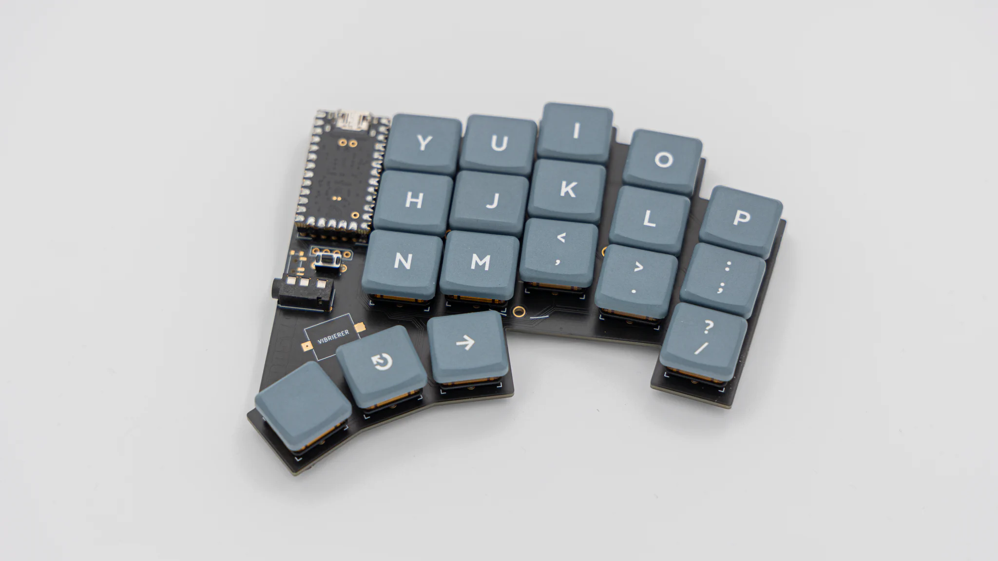
And your DASBOB keyboard is done!