Assembly
Let’s start the assembly with the PCB.
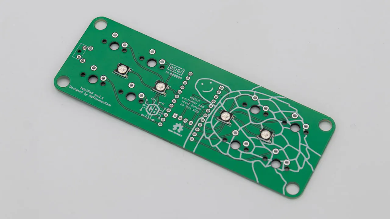
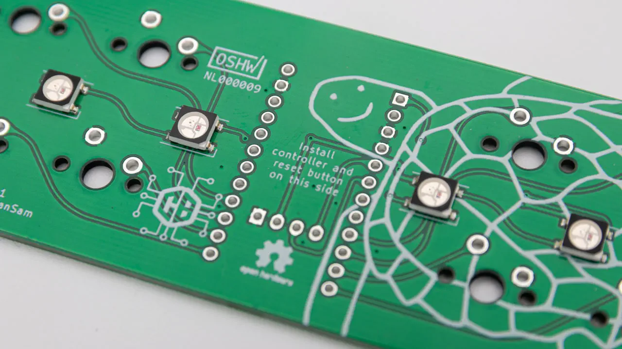
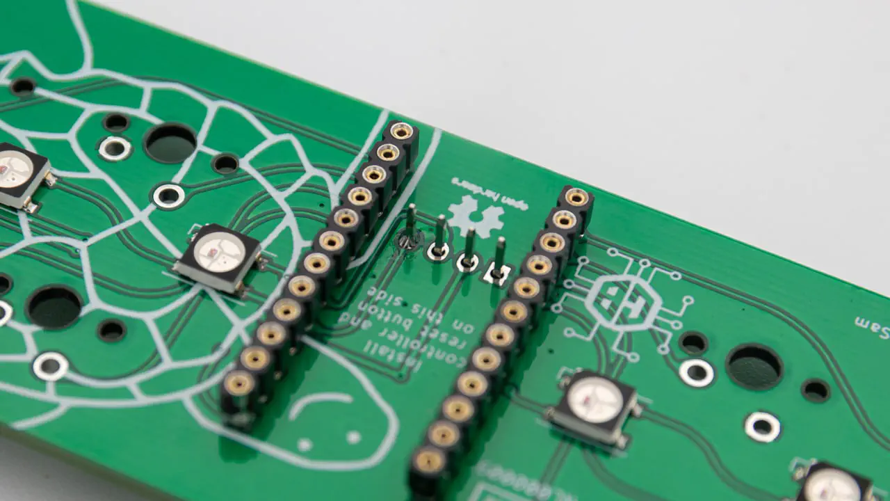
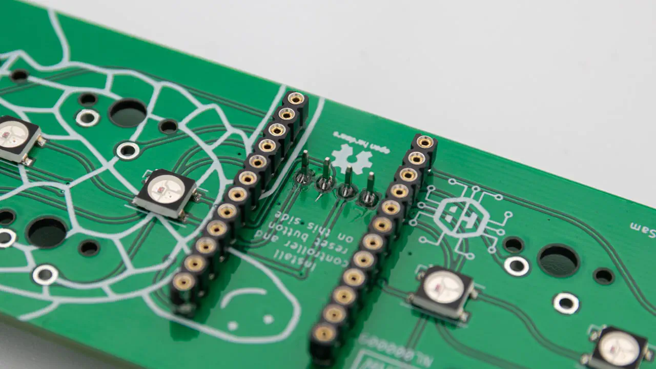
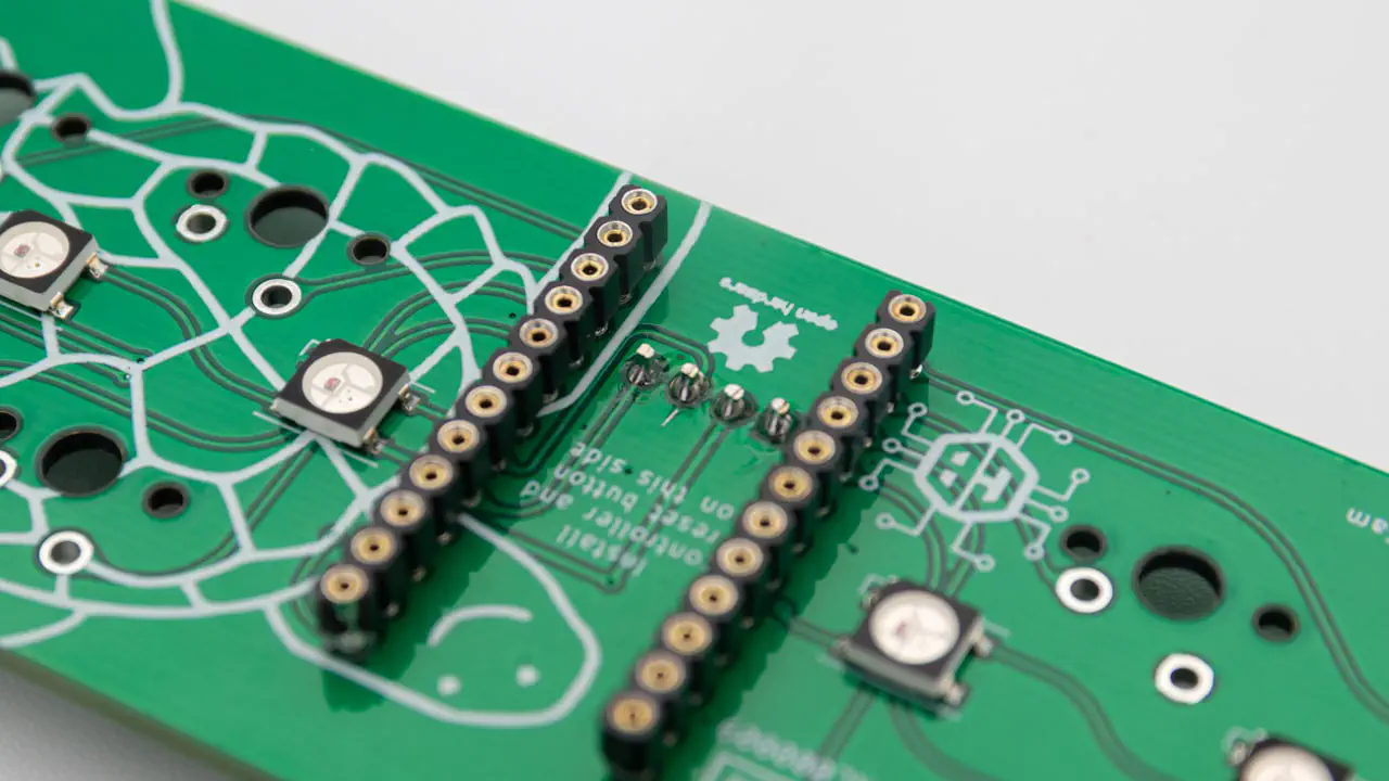
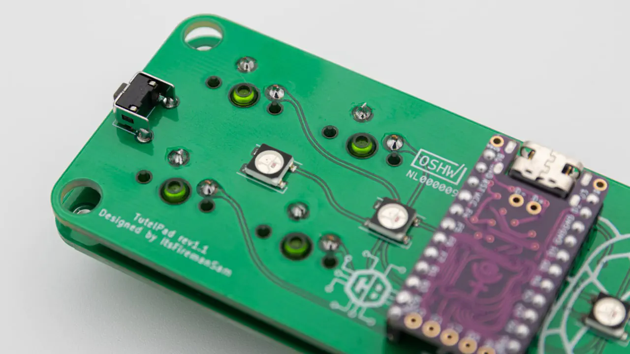
The first step is to solder in the header pins for the controller. Instructions can be found here. On the PCB you will see text, indicating on which side which component is supposed to go.
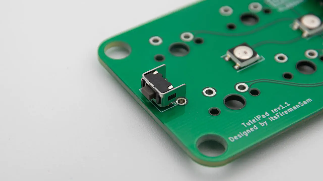
Now solder in the reset button. Again, please pay attention on which side of the PCB you have to solder it on.
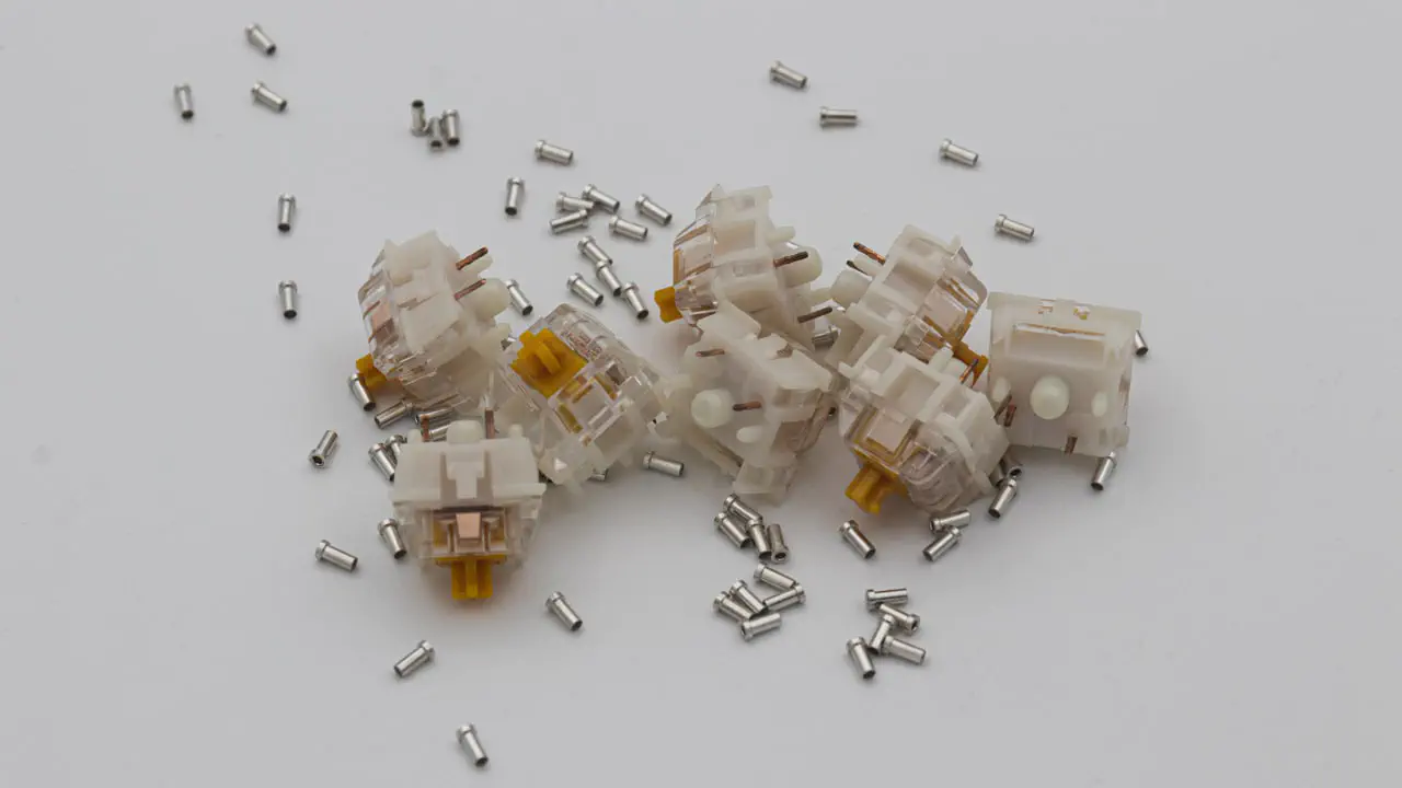
Now is also a good time to solder in Mill-Max sockets if you want to. Instructions on how to do that can be found here.
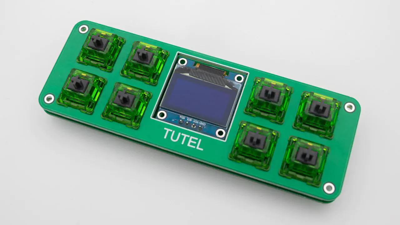
Next solder in the OLED. This goes on the opposite side of the controller. The OLED should sit straight in the cutout in the switch plate afterwards, so solder only one pin at first.
Align the OLED before soldering the rest. Heat up the one pin and make the OLED straight.
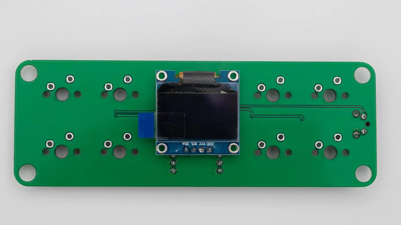
Now you can solder in the other 3 pins.
Clip off the pins of the OLED on the other side. Otherwise the controller will not fit.
You have to flash the controller. You can find the firmware here. And instructions on how to flash a controller here.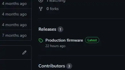
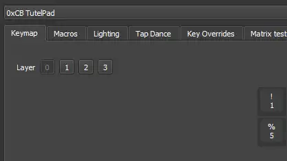
It is good practice to confirm the PCB working after you flashed the controller. So plug it in the computer and see if you can get it to show up in VIAL.
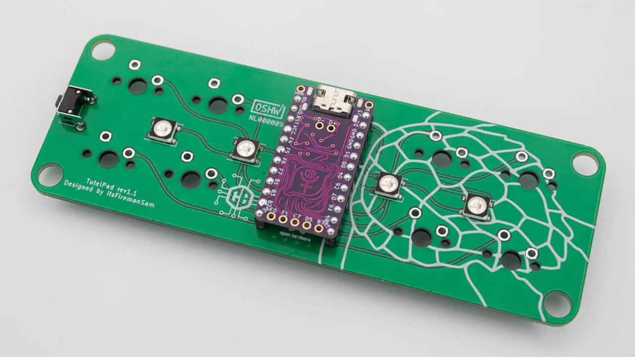
If your controller is working, you can solder it in. Instructions on how to do that can be found here. When you have the PCB in front of you so that you can read the text on it, the USB port should go to the top of the PCB. You should not see the components of the micro controller, when it is sitting in the PCB.
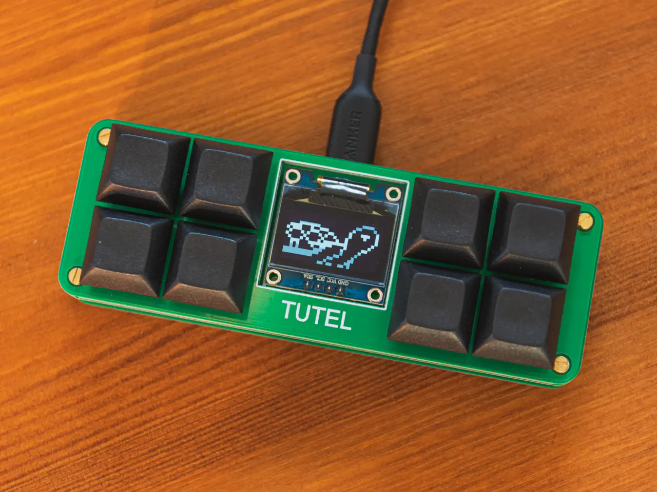
Insert the Switches into the switch plate. You can use the switch plate both ways around either with or without the TUTEL writing.
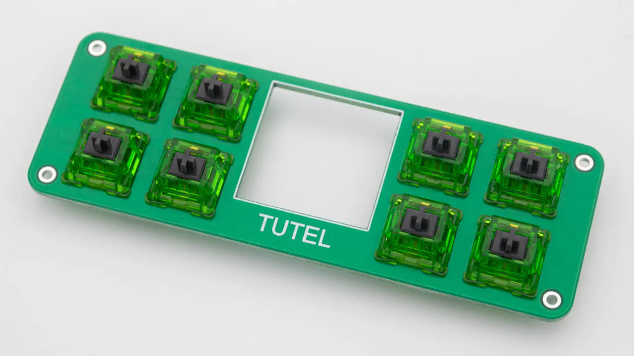
And put the PCB onto the switches.
When you are not using Mill-Max sockets you will have to solder in the switches now.
Screw in the 4 standoffs into the switch plate.
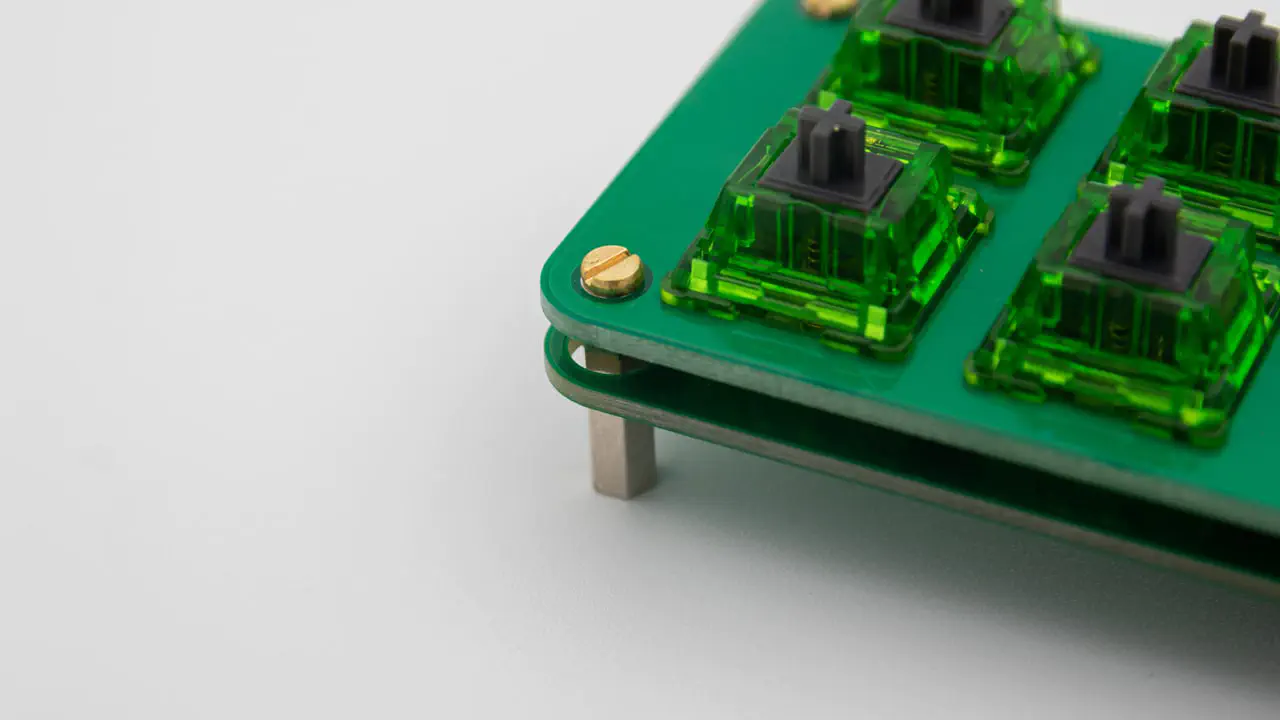
Then place the bottom plate on them and screw them in from the bottom. You can reverse the bottom plate so you can use it with or without the TUTEL writing on there.
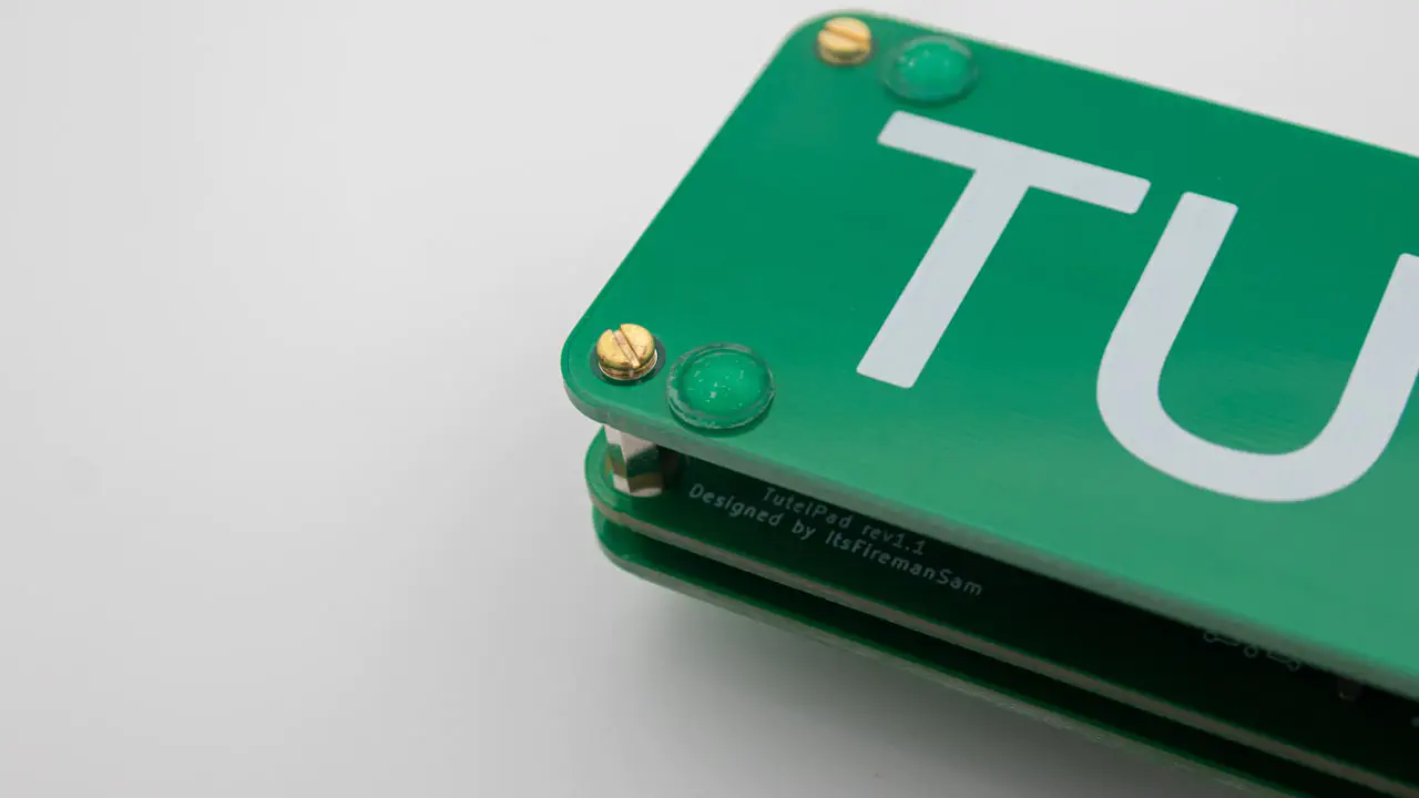
Now add the rubber feet.
The only thing left to do is to add Keycaps to your MacroPad.
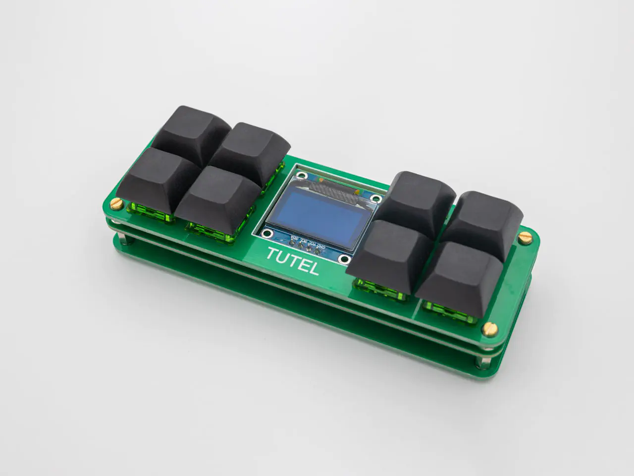
And you are done with your TutelPad!